BRAKE BOOSTER PUMP(for RHD) INSTALLATION
PROCEDURE
-
INSTALL BRAKE BOOSTER PUMP ASSEMBLY
-
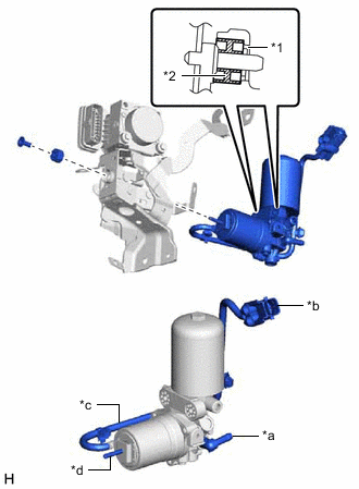
*1 Brake Booster Pump Collar *2 Brake Booster Pump Bushing *a Union *b Connector *c Wire Harness *d Stud Install the brake booster pump assembly, brake booster pump bushing and brake actuator case collar to the brake actuator bracket assembly.
Note
-
Do not drop the brake booster pump assembly when carrying it.
-
Be careful not to allow brake fluid to enter the connector.
-
When installing the brake booster pump assembly to the brake actuator bracket assembly, confirm that the 2 brake booster pump bushings and 2 brake booster pump collars are on the brake booster pump assembly.
-
If installing a new brake booster pump assembly, do not remove the hole plugs before connecting the brake lines because the brake booster pump assembly is filled with brake fluid.
-
Do not carry the brake booster pump assembly by the parts shown in the illustration.
-
-
Install the nut.
- Torque:
- 5.4 N*m { 55 kgf*cm, 48 in.*lbf }
-
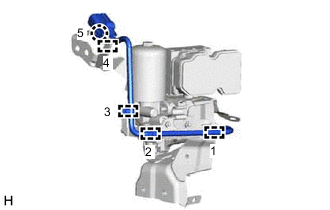
Engage the claw and 4 clamps to install the brake booster pump assembly wire harness to the brake actuator assembly bracket.
Note
Engage the clamps and claw in the order shown in the illustration.
-
-
INSTALL NO. 1 BRAKE TUBE CLAMP BRACKET
-
Install the No. 1 brake tube clamp bracket to the brake booster pump assembly with the bolt.
- Torque:
- 7.0 N*m { 71 kgf*cm, 62 in.*lbf }
-
-
INSTALL NO. 1 BRAKE ACTUATOR HOSE
-
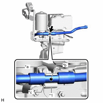
*1 Brake Actuator Hose Clamp *a Protector *b Identification Mark *c Contacts Install the No. 1 brake actuator hose to the brake actuator hose clamp.
Note
-
Make sure to install the No. 1 brake actuator hose so that the protector on the brake booster pump assembly side contacts the brake actuator hose clamp.
-
Make sure to install the No. 1 brake actuator hose so that its identification mark can be seen.
-
-
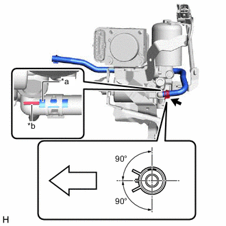
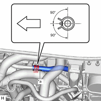
*a Identification Mark *b Rib of Brake Booster Pump Assembly Port 
Front of the vehicle Install the No. 1 brake actuator hose to the brake booster pump assembly, and slide the clip to secure it.
Note
-
When installing the No. 1 brake actuator hose, make sure to align its alignment mark with the rib of the brake booster pump assembly.
-
Install the clip within the range shown in the illustration.
-
-
-
INSTALL BRAKE ACTUATOR WITH BRAKE BOOSTER PUMP ASSEMBLY
-
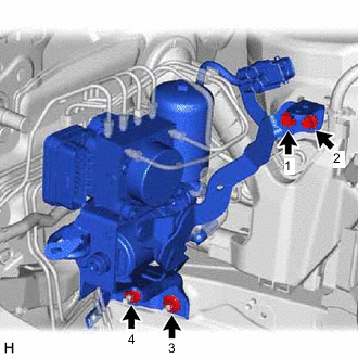
Install the brake actuator with brake booster pump assembly to the vehicle body with the 2 bolts and 2 nuts.
- Torque:
- 19 N*m { 194 kgf*cm, 14 ft.*lbf }
Note
-
Tighten the bolts and nuts in the order shown in the illustration.
-
Do not apply excessive force to the brake lines.
-
Do not hold the brake booster pump assembly by the connector, union or wire harness.
-
Do not hold the brake actuator assembly by the connector.
-
Do not drop the brake actuator with brake booster pump assembly when carrying it.
Tech Tips
Install the brake actuator with brake booster pump assembly while avoiding the brake lines.
-
Engage the clamp to install the brake tube clamp to the brake actuator bracket assembly.
-
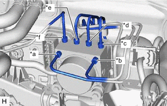
*a From 1st Chamber of Brake Booster with Master Cylinder Assembly *b From 2nd Chamber of Brake Booster with Master Cylinder Assembly *c To Front Wheel Cylinder Assembly LH *d To Rear Wheel Cylinder Assembly RH *e To Rear Wheel Cylinder Assembly LH *f To Front Wheel Cylinder Assembly RH Temporarily tighten the 6 brake lines to the correct positions on the brake actuator assembly as shown in the illustration.
-

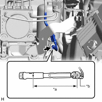
*a Torque Wrench Fulcrum Length *b Union Nut Wrench Using a union nut wrench, fully tighten the 6 brake lines.
- Torque:
- Specified tightening torque
- 15.2 N*m { 155 kgf*cm, 11 ft.*lbf }
Note
-
Do not kink or damage the brake lines.
-
Do not allow the brake lines to twist or interfere with other parts or the vehicle body during tightening.
-
Do not allow any foreign matter such as dirt or dust to enter the brake lines from the connecting parts.
Tech Tips
-
Calculate the torque wrench reading when changing the fulcrum length of the torque wrench.
-
When using a union nut wrench (fulcrum length of 22 mm (0.866 in.)) + torque wrench (fulcrum length of 162 mm (6.38 in.)):
13.38 N*m (136 kgf*cm, 10 ft.*lbf)
-
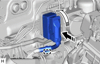

Connect the connector 
Lock the lock lever Connect the connector to the brake actuator assembly and lock the lock lever as shown in the illustration.
Note
-
Make sure that the connector is locked securely.
-
Make sure that the connector can be connected smoothly. Do not allow water, oil or dirt to enter.
-
-
Engage the clamp to install the wire harness.
-
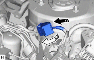
Connect the connector Lock the lock lever Connect the connector to the brake booster pump assembly and lock the lock lever as shown in the illustration.
Note
-
Make sure that the connector is locked securely.
-
Make sure that the connector can be connected smoothly. Do not allow water, oil or dirt to enter.
-
-
-
INSTALL ACCUMULATOR TO BRAKE MASTER CYLINDER TUBE
-
Temporarily tighten the accumulator to brake master cylinder tube to the brake booster pump assembly.
-
Install the accumulator to brake master cylinder tube with the bolt.
- Torque:
- 7.0 N*m { 71 kgf*cm, 62 in.*lbf }
-
*a Torque Wrench Fulcrum Length *b Union Nut Wrench Using a union nut wrench, tighten the accumulator to brake master cylinder tube.
- Torque:
- Specified tightening torque
- 15.2 N*m { 155 kgf*cm, 11 ft.*lbf }
Note
-
Do not kink or damage the accumulator to brake master cylinder tube.
-
Do not allow the accumulator to brake master cylinder tube to twist or interfere with other parts or the vehicle body during tightening.
-
Do not allow any foreign matter such as dirt or dust to enter the accumulator to brake master cylinder tube from the connecting parts.
Tech Tips
-
Calculate the torque wrench reading when changing the fulcrum length of the torque wrench.
-
When using a union nut wrench (fulcrum length of 22 mm (0.866 in.)) + torque wrench (fulcrum length of 162 mm (6.38 in.)):
13.38 N*m (136 kgf*cm, 10 ft.*lbf)
-
-
INSTALL NO. 1 BRAKE ACTUATOR HOSE
-
*a Identification Mark Front of the vehicle Connect the No. 1 brake actuator hose to the No. 1 brake actuator tube to install it, and slide the clip to secure it.
Note
-
Make sure to connect the No. 1 brake actuator hose with its identification mark facing the front of the vehicle.
-
Install the clip within the range shown in the illustration.
-
-
-
BLEED NO. 1 BRAKE ACTUATOR TUBE
-
FILL RESERVOIR WITH BRAKE FLUID
-
INSTALL ENGINE ASSEMBLY WITH TRANSAXLE
-
BLEED BRAKE SYSTEM