BRAKE BOOSTER PUMP(for RHD) REMOVAL
CAUTION / NOTICE / HINT
The necessary procedures (adjustment, calibration, initialization, or registration) that must be performed after parts are removed, installed, or replaced during brake booster pump assembly removal/installation are shown below.
| Replaced Part or Performed Procedure | Necessary Procedure | Effect/Inoperative Function when Necessary Procedure not Performed | Link |
|---|---|---|---|
| Auxiliary battery terminal is disconnected/reconnected | Memorize steering angle neutral point | Lane departure alert system (w/ Steering control) | |
| Intelligent clearance sonar system | |||
| Simple intelligent parking assist system | |||
| Pre-crash safety system | |||
| Adaptive high beam system | |||
| Parking assist monitor system | |||
| Initialize back door lock | Power door lock control system | ||
| Suspension, tires, etc. (The vehicle height changes because of suspension or tire replacement) |
Initialize No. 1 headlight ECU sub-assembly LH |
|
|
|
|
||
| Rear television camera assembly optical axis (Back camera position setting) | Parking assist monitor system | ||
| Front wheel alignment adjustment |
|
|
CAUTION / NOTICE / HINT
Note
While the auxiliary battery is connected, even if the power switch is off, the brake control system activates when the brake pedal is depressed or any door courtesy switch turns on. Therefore, when servicing the brake system components, do not operate the brake pedal or open/close the doors while the auxiliary battery is connected.
PROCEDURE
-
PERFORM ACCUMULATOR PRESSURE ZERO DOWN
-
REMOVE ENGINE ASSEMBLY WITH TRANSAXLE
-
DRAIN BRAKE FLUID
Note
If brake fluid leaks onto any painted surface, immediately wash it off.
-
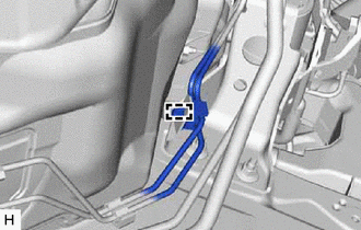
SEPARATE NO. 1 BRAKE ACTUATOR HOSE
-
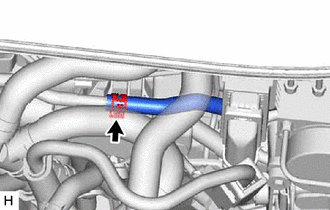
Slide the clip and separate the No. 1 brake actuator hose from the No. 1 brake actuator tube.
-
-
SEPARATE ACCUMULATOR TO BRAKE MASTER CYLINDER TUBE
-
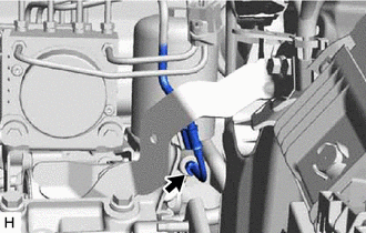
Using a union nut wrench, disconnect the accumulator to brake master cylinder tube from the brake booster pump assembly.
-
Remove the bolt to separate the accumulator to brake master cylinder tube.
-
-
REMOVE BRAKE ACTUATOR WITH BRAKE BOOSTER PUMP ASSEMBLY
-

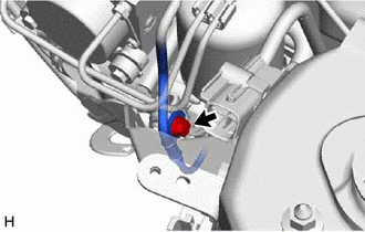
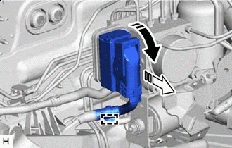
Release the lock lever 
Disconnect the connector Release the lock lever and disconnect the connector from the brake booster pump assembly as shown in the illustration.
Note
Be careful not to allow any brake fluid to enter the connector.
-
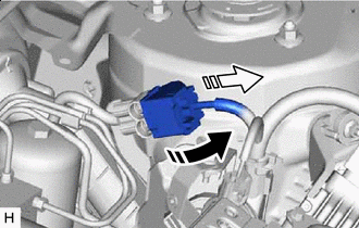
Release the lock lever Disconnect the connector Release the lock lever and disconnect the connector from the brake actuator assembly as shown in the illustration.
Note
Be careful not to allow any brake fluid to enter the connector.
-
Disengage the clamp and separate the engine room main wire.
-
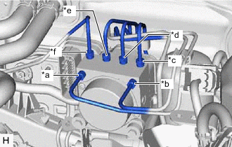
*a From 1st Chamber of Brake Booster with Master Cylinder Assembly *b From 2nd Chamber of Brake Booster with Master Cylinder Assembly *c To Front Wheel Cylinder Assembly LH *d To Rear Wheel Cylinder Assembly RH *e To Rear Wheel Cylinder Assembly LH *f To Front Wheel Cylinder Assembly RH Use tags or make a memo to identify the places to reconnect the brake lines.
-
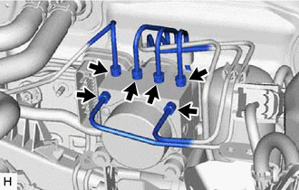
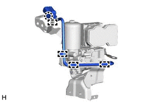
Using a union nut wrench, disconnect the 6 brake lines from the brake actuator assembly.
-
Disengage the clamp to separate the brake tube clamp from the brake actuator bracket assembly.
-
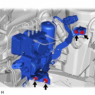
Remove the 2 bolts, 2 nuts and brake actuator with brake booster pump assembly from the vehicle body.
Note
-
Do not apply excessive force to the brake lines.
-
Be careful not to allow any brake fluid to enter the connector.
-
Do not hold the brake booster pump assembly by the connector, union or wire harness.
-
Do not hold the brake actuator assembly by the connector.
-
Do not drop the brake actuator with brake booster pump assembly when carrying it.
Tech Tips
Remove the brake actuator with brake booster pump assembly while avoiding the brake lines.
-
-
-
REMOVE NO. 1 BRAKE ACTUATOR HOSE
-
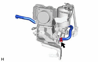
Slide the clip and remove the No. 1 brake actuator hose from the brake booster pump assembly.
-
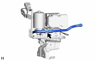
Remove the No. 1 brake actuator hose from the brake actuator hose clamp.
-
-
REMOVE NO. 1 BRAKE TUBE CLAMP BRACKET
-
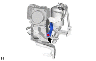
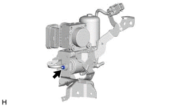
Remove the bolt and No. 1 brake tube clamp bracket from the brake booster pump assembly.
-
-
REMOVE BRAKE BOOSTER PUMP ASSEMBLY
-
Disengage the claw and 4 clamps to separate the brake booster pump assembly wire harness from the brake actuator assembly bracket.
-
Remove the nut from the brake booster pump assembly.
-
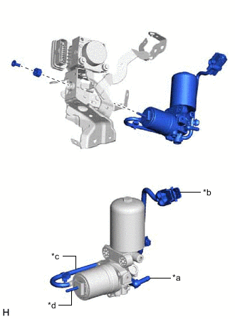
*a Union *b Connector *c Wire Harness *d Stud Remove the brake booster pump assembly, brake booster pump bushing and brake actuator case collar from the brake actuator bracket assembly.
Note
-
Do not carry the brake booster pump assembly by the parts shown in the illustration.
-
Do not drop the brake booster pump assembly when carrying it.
-
Be careful not to allow brake fluid to enter the connector.
-
-