BRAKE BOOSTER PUMP(for LHD) INSTALLATION
PROCEDURE
-
INSTALL NO. 1 BRAKE TUBE CLAMP BRACKET
-
Install the No. 1 brake tube clamp bracket to the brake booster pump assembly with the bolt.
- Torque:
- 7.0 N*m { 71 kgf*cm, 62 in.*lbf }
-
-
INSTALL NO. 1 BRAKE ACTUATOR HOSE
-
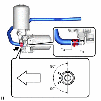
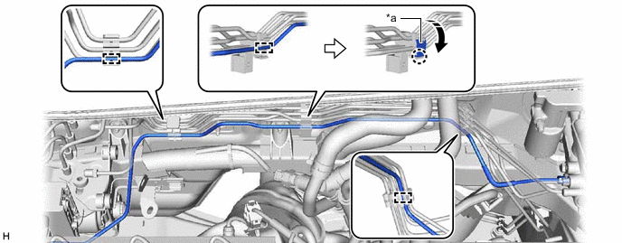
*a Alignment Mark *b Rib of Brake Booster Pump Assembly Port 
Front of the vehicle Install the No. 1 brake actuator hose to the brake booster pump assembly, and slide the clip to secure it.
Note
-
When installing the No. 1 brake actuator hose, make sure to align its alignment mark with the rib of the brake booster pump assembly.
-
Install the clip within the range shown in the illustration.
-
-
-
INSTALL BRAKE BOOSTER PUMP ASSEMBLY
-
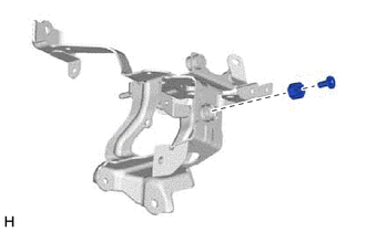
Install the brake actuator case collar and brake booster pump bushing to the brake actuator bracket assembly.
-
Temporarily install the brake actuator bracket assembly to the vehicle body.
Note
Do not apply excessive force to the brake lines.
-
Temporarily install the brake booster pump assembly as shown in the illustration.
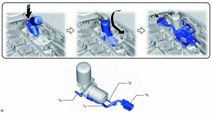
*a Union *b Connector *c Wire Harness *d Stud 
Install in this Direction - - Note
-
Do not apply excessive force to the brake lines.
-
Do not drop the brake booster pump assembly when carrying it.
-
Be careful not to allow brake fluid to enter the connector.
-
If installing a new brake booster pump assembly, do not remove the hole plugs before connecting the brake lines because the brake booster pump assembly is filled with brake fluid.
-
Do not carry the brake booster pump assembly by the parts shown in the illustration.
Tech Tips
-
Move the brake actuator bracket assembly as necessary to allow the brake booster pump assembly to be temporarily installed.
-
Make sure to only temporarily install the brake booster pump assembly as the brake actuator assembly needs to be installed first.
-
-
Install the brake actuator bracket assembly with the bolt.
- Torque:
- 19 N*m { 194 kgf*cm, 14 ft.*lbf }
-
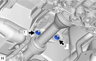
Install the 2 nuts.
- Torque:
- 19 N*m { 194 kgf*cm, 14 ft.*lbf }
Note
Tighten the nuts in the order shown in the illustration.
-
Engage the clamp to install the No. 3 front brake tube to the brake actuator bracket assembly.
-
-
INSTALL ACCUMULATOR TO BRAKE MASTER CYLINDER TUBE
-
Engage the 3 clamps to install the accumulator to brake master cylinder tube.
*a Clamp Cover - - -
Engage the claw to install the clamp cover.
-
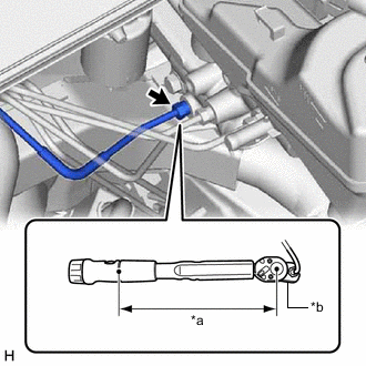
*a Torque Wrench Fulcrum Length *b Union Nut Wrench Using a union nut wrench, connect the accumulator to brake master cylinder tube to the brake booster with master cylinder assembly.
- Torque:
- Specified tightening torque
- 15.2 N*m { 155 kgf*cm, 11 ft.*lbf }
Note
-
Do not kink or damage the accumulator to brake master cylinder tube.
-
Do not allow the accumulator to brake master cylinder tube to twist or interfere with other parts or the vehicle body during tightening.
-
Do not allow any foreign matter such as dirt or dust to enter the accumulator to brake master cylinder tube from the connecting parts.
Tech Tips
-
Calculate the torque wrench reading when changing the fulcrum length of the torque wrench.
-
When using a union nut wrench (fulcrum length of 22 mm (0.866 in.)) + torque wrench (fulcrum length of 162 mm (6.38 in.)):
13.38 N*m (136 kgf*cm, 10 ft.*lbf)
-
-
INSTALL NO. 1 BRAKE ACTUATOR TUBE
-
Install the No. 1 brake actuator tube with the 2 nuts.
- Torque:
- 8.5 N*m { 87 kgf*cm, 75 in.*lbf }
-
-
INSTALL BRAKE ACTUATOR ASSEMBLY