BRAKE BOOSTER(for LHD) INSTALLATION

PROCEDURE
-
INSTALL BRAKE MASTER CYLINDER GASKET
-
Install a new brake master cylinder gasket to the brake booster with master cylinder assembly.
-
-
INSTALL BRAKE BOOSTER WITH MASTER CYLINDER ASSEMBLY
-
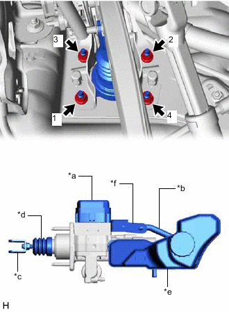
*a Skid Control ECU *b No. 1 Reservoir Hose *c Brake Master Cylinder Push Rod Clevis *d Boot *e Master Cylinder Reservoir Assembly *f Brake Actuator Bracket Install the brake booster with master cylinder assembly with the 4 nuts.
- Torque:
- 12.7 N*m { 130 kgf*cm, 9 ft.*lbf }
Note
-
Tighten the nuts in the order shown in the illustration.
-
Do not kink or damage the brake lines.
-
Do not carry the brake booster with master cylinder assembly by the parts shown in the illustration.
-
Be careful not to allow brake fluid to enter the connector.
-
If installing a new brake booster with master cylinder assembly, do not remove the hole plugs before connecting the brake lines because the brake booster with master cylinder is filled with brake fluid.
-
-
INSTALL PUSH ROD PIN
-
INSTALL BRAKE PEDAL RETURN SPRING
-
CONNECT BRAKE LINE
-
Engage the clamp to install the 3 brake lines.
Note
-
Do not damage the clamp.
-
Do not kink or damage the brake lines.
-
-
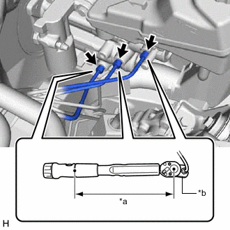
*a Torque Wrench Fulcrum Length *b Union Nut Wrench Using a union nut wrench, connect the 3 brake lines to the brake booster with master cylinder assembly.
- Torque:
- Specified tightening torque
- 15.2 N*m { 155 kgf*cm, 11 ft.*lbf }
Note
-
Do not kink or damage the brake lines.
-
Do not allow the brake lines to twist or interfere with other parts or the vehicle body during tightening.
-
Do not allow any foreign matter such as dirt or dust to enter the brake lines from the connecting parts.
Tech Tips
-
Calculate the torque wrench reading when changing the fulcrum length of the torque wrench.
-
When using a union nut wrench (fulcrum length of 22 mm (0.866 in.)) + torque wrench (fulcrum length of 162 mm (6.38 in.)):
13.38 N*m (136 kgf*cm, 10 ft.*lbf)
-
-
CONNECT NO. 2 BRAKE ACTUATOR HOSE
-
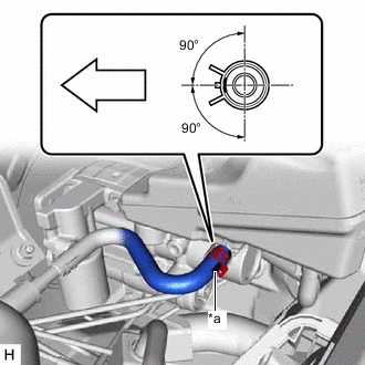
*a Identification Mark 
Front of the vehicle Connect the No. 2 brake actuator hose to the brake booster with master cylinder assembly, and slide the clip to secure it.
Note
-
Make sure to connect the No. 2 brake actuator hose with its identification mark facing the front of the vehicle.
-
Install the clip within the range shown in the illustration.
-
-
-
CONNECT ENGINE ROOM MAIN WIRE
-
Connect the connector to the brake booster with master cylinder assembly.
-
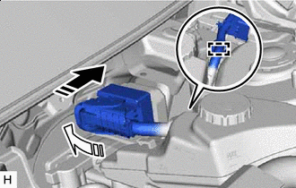

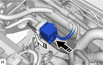
Connect the connector 
Lock the lock lever Connect the connector to the brake booster with master cylinder assembly and lock the lock lever as shown in the illustration.
Note
-
Make sure that the connector is locked securely.
-
Make sure that the connector can be connected smoothly. Do not allow water, oil or dirt to enter the connector.
-
-
Engage the clamp to install the engine room main wire.
-
-
CONNECT ENGINE WIRE (w/o Canister Pump Module)
-
INSTALL NO. 1 ENGINE COVER SUB-ASSEMBLY (w/o Canister Pump Module)
-
BLEED NO. 1 BRAKE ACTUATOR TUBE
Note
Make sure to bleed the air from the No. 1 brake actuator tube. If the air remains in the No. 1 brake actuator tube, the air will enter the brake booster pump assembly and may damage the brake booster pump assembly.
-
Remove the brake master cylinder reservoir filler cap assembly.
-
Add brake fluid to the reservoir until the fluid level is between the MAX and MIN lines on the brake fluid reservoir.
Brake Fluid SAE J1703 or FMVSS No. 116 DOT3 SAE J1704 or FMVSS No. 116 DOT4 -
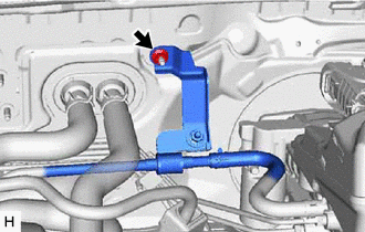
Remove the nut to separate the No. 1 brake actuator tube.
Tech Tips
If the No. 1 brake actuator tube has already been separated, it is not necessary to perform this step.
-
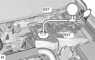
Set SST to the brake master cylinder reservoir assembly.
- SST
- 09992-00242
-
Using SST, increase and then maintain the pressure in the brake master cylinder reservoir assembly for 60 seconds.(*1)
Standard Pressure 50 to 80 kPa (0.6 to 0.8 kgf/cm2, 7.3 to 11.6 psi) -
Release the pressure in the brake master cylinder reservoir assembly and wait for 30 seconds.(*2)
-
Repeat steps *1 to *2, 3 times.
-
Remove SST.
-
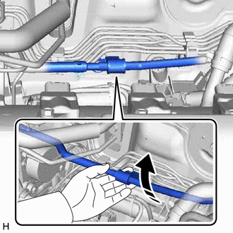
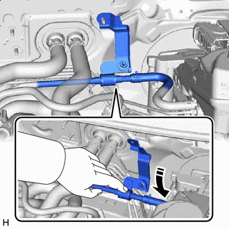
Pull up Pull up the No. 1 brake actuator tube as shown in the illustration as high as possible for 10 seconds without damaging the bracket of the No. 1 brake actuator tube.(*3)
Note
Do not damage the hoses.
Tech Tips
Elevating the No. 2 brake actuator hose causes any air in the horizontal portion of the hose to flow to the brake master cylinder reservoir assembly side.
-
Repeat step *3, 5 times.
-
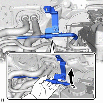
Pull up Elevate the No. 1 brake actuator tube for 10 seconds by lifting the No. 1 brake actuator tube as shown in the illustration.(*4)
Note
Do not damage the hoses.
Tech Tips
Elevating the No. 1 brake actuator tube causes any air in the horizontal portion of the tube to flow to the brake master cylinder reservoir assembly side.
-
Press down Lower the No. 1 brake actuator tube for 10 seconds as shown in the illustration.(*5)
Note
Do not damage the hoses.
Tech Tips
Lowering the No. 1 brake actuator tube causes any air in the No. 1 brake actuator tube to flow to the brake master cylinder reservoir assembly side.
-
Repeat steps *4 to *5, 5 times.
-
Install the No. 1 brake actuator tube with the nut.
- Torque:
- 8.5 N*m { 87 kgf*cm, 75 in.*lbf }
-
-
CONNECT BRAKE BOOSTER PUMP CONNECTOR
Tech Tips
Perform this operation only when the accumulator pressure zero down could not be performed using the GTS.
-
Connect the connector Lock the lock lever Connect the connector to the brake booster pump assembly and lock the lock lever as shown in the illustration.
Note
-
Make sure that the connector is locked securely.
-
Make sure that the connector can be connected smoothly. Do not allow water, oil or dirt to enter the connector.
-
-
-
FILL RESERVOIR WITH BRAKE FLUID
-
CONNECT CABLE TO NEGATIVE AUXILIARY BATTERY TERMINAL
-
BLEED BRAKE SYSTEM
-
INSPECT AND ADJUST BRAKE PEDAL
-
OBTAIN ZERO POINT OF YAW RATE AND ACCELERATION SENSOR
-
INSTALL NO. 1 INSTRUMENT PANEL UNDER COVER SUB-ASSEMBLY
-
INSTALL COWL SIDE TRIM BOARD LH
-
INSTALL FRONT DOOR SCUFF PLATE LH
-
INSTALL OUTER COWL TOP PANEL SUB-ASSEMBLY
-
INSTALL COWL BODY MOUNTING REINFORCEMENT LH
-
INSTALL WATER GUARD PLATE
-
INSTALL NO. 1 HEATER AIR DUCT SPLASH SHIELD SEAL
-
INSTALL WINDSHIELD WIPER MOTOR AND LINK ASSEMBLY