BRAKE PEDAL(for RHD) REMOVAL
CAUTION / NOTICE / HINT
The necessary procedures (adjustment, calibration, initialization, or registration) that must be performed after parts are removed, installed, or replaced during brake pedal support assembly removal/installation are shown below.
| Replaced Part or Performed Procedure | Necessary Procedure | Effect/Inoperative Function when Necessary Procedure not Performed | Link |
|---|---|---|---|
| Auxiliary battery terminal is disconnected/reconnected | Memorize steering angle neutral point | Lane departure alert system (w/ Steering control) | |
| Intelligent clearance sonar system | |||
| Simple intelligent parking assist system | |||
| Pre-crash safety system | |||
| Adaptive high beam system | |||
| Parking assist monitor system | |||
| Initialize back door lock | Power door lock control system | ||
| Replacement of brake pedal support assembly |
|
|
Click here for Initialization Click here for Calibration |
| Removal/installation of the steering sensor | Steering angle neutral point (Initialize intelligent clearance sonar system) |
|
|
| Steering angle setting | Parking assist monitor system |
CAUTION / NOTICE / HINT
Note
While the auxiliary battery is connected, even if the power switch is off, the brake control system activates when the brake pedal is depressed or any door courtesy switch turns on. Therefore, when servicing the brake system components, do not operate the brake pedal or open/close the doors while the auxiliary battery is connected.
PROCEDURE
-
REMOVE LOWER INSTRUMENT PANEL SUB-ASSEMBLY
-
REMOVE STEERING COLUMN ASSEMBLY
-
REMOVE BRAKE PEDAL STROKE SENSOR ASSEMBLY
-
REMOVE STOP LIGHT SWITCH MOUNTING ADJUSTER
-
REMOVE BRAKE PEDAL RETURN SPRING
-
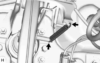
Remove the brake pedal return spring from the brake pedal support assembly and push rod pin.
-
-
REMOVE PUSH ROD PIN
-
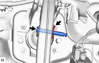
Remove the clip and push rod pin to separate the brake pedal support assembly from the brake master cylinder push rod clevis.
-
-
REMOVE BRAKE PEDAL SUPPORT ASSEMBLY
-
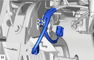
Disengage the clamp to separate the wire harness from the brake pedal support assembly.
-
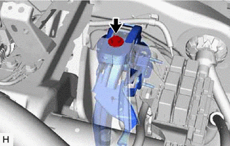
Remove the bolt and separate the brake pedal support assembly from the instrument panel reinforcement assembly.
-
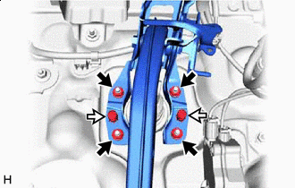

Nut 
Clip Remove the 2 clips.
-
Remove the 4 nuts and brake pedal support assembly.
-
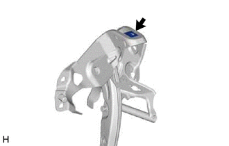
Remove the nut from the brake pedal support assembly.
-
-
REMOVE BRAKE PEDAL PAD
-
Remove the brake pedal pad from the brake pedal support assembly.
-