BRAKE PEDAL(for LHD) ADJUSTMENT
PROCEDURE
-
INSPECT AND ADJUST BRAKE PEDAL HEIGHT
-
Remove the front door scuff plate LH.
-
Remove the cowl side trim board LH.
-
Check the brake pedal height.
Note
-
Inspect and adjust the brake pedal height with the floor carpet folded back.
-
When performing the measurement, make sure that the measuring device is contacting the surface of the dash panel insulator assembly clip.
-
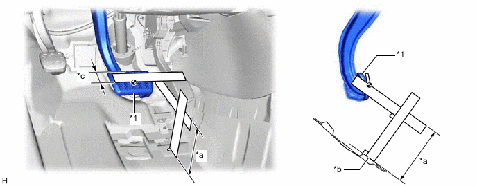
Measure the shortest distance between the brake pedal pad surface and dash panel insulator assembly clip.
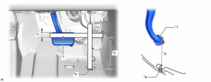
*1 Brake Pedal Pad - - *a Brake Pedal Height *b Dash Panel Insulator Assembly Clip *c 30 mm (1.18 in.) - - Brake Pedal Height from Dash Panel Insulator Assembly Clip 174.3 to 184.3 mm (6.86 to 7.26 in.) If the pedal height is not as specified, adjust the brake pedal height according to the procedure below.
-
-
Adjust the brake pedal height.
-
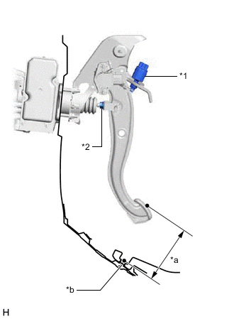
*1 Stop Light Switch Assembly *2 Lock Nut *a Brake Pedal Height *b Dash Panel Insulator Assembly Clip Remove the stop light switch assembly.
-
Loosen the lock nut.
-
Adjust the brake pedal height by turning the push rod.
Brake Pedal Height from Dash Panel Insulator Assembly Clip 174.3 to 184.3 mm (6.86 to 7.26 in.) -
Tighten the lock nut.
- Torque:
- 25.5 N*m { 260 kgf*cm, 19 ft.*lbf }
-
Install the stop light switch assembly.
-
-
Install the cowl side trim board LH.
-
Install the front door scuff plate LH.
-
-
INSPECT AND ADJUST BRAKE PEDAL STROKE SENSOR ASSEMBLY
-
Inspect the brake pedal stroke sensor assembly.
-
Connect the GTS to the DLC3 with the power switch off.
-
Turn the power switch on (IG).
-
Turn the GTS on and enter the following menus: Chassis / ABS/VSC/TRC / Data List / Stroke Sensor.
Chassis > ABS/VSC/TRC > Data ListTester Display Stroke Sensor -
Read the stroke sensor value without the brake pedal depressed.
Standard Voltage (without the brake pedal depressed) 0.8 to 1.2 V If the stroke sensor value is not within the standard voltage, adjust the brake pedal stroke sensor assembly.
-
-
Adjust the brake pedal stroke sensor assembly.
-
Remove the front door scuff plate LH.
-
Remove the cowl side trim board LH.
-
Remove the No. 1 instrument panel under cover sub-assembly.
-
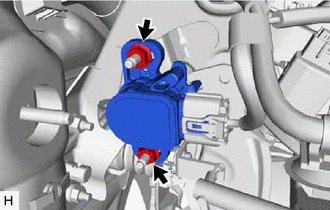
Loosen the 2 nuts.
Note
Do not depress the brake pedal after turning the power switch on (IG).
-
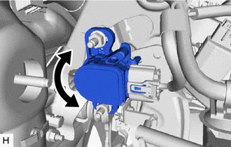
Read the stroke sensor value in the Data List, and turn the brake pedal stroke sensor assembly slowly to the right or left to adjust the output voltage so that it is within the following range.
Standard Voltage (without the brake pedal depressed) 0.8 to 1.2 V -
Tighten the 2 nuts.
- Torque:
- 8.5 N*m { 87 kgf*cm, 75 in.*lbf }
-
Turn the GTS off and turn the power switch off.
-
Disconnect the GTS.
-
Install the No. 1 instrument panel under cover sub-assembly.
-
Install the cowl side trim board LH.
-
Install the front door scuff plate LH.
-
-
Perform linear solenoid valve offset learning, ABS holding solenoid valve learning, brake pedal stroke sensor assembly zero point calibration and system information memorization.
-
-
INSPECT BRAKE PEDAL FREE PLAY
-
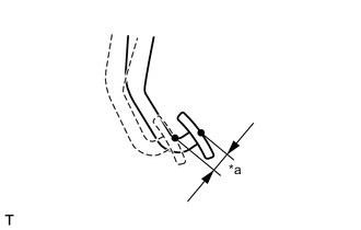
*a Brake Pedal Free Play Depress the brake pedal until a slight resistance is felt. Measure the brake pedal free play as shown in the illustration.
Brake Pedal Free Play 1.0 to 6.0 mm (0.0394 to 0.236 in.) If the pedal free play is not as specified, check the stop light switch clearance.
If the pedal free play is as specified, proceed to the Inspect Brake Pedal Reserve Distance procedure.
-
-
INSPECT BRAKE PEDAL RESERVE DISTANCE
-
Remove the front door scuff plate LH.
-
Remove the cowl side trim board LH.
-
Turn back the front floor carpet assembly.
-
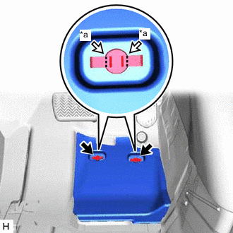
*a Cut Cut each claw of the 2 clips and remove the No. 1 dash panel insulator pad.
Note
If the No. 1 dash panel insulator pad is damaged, replace it with a new one.
-
Remove the 2 clips.
-
With the power switch on (READY), depress the brake pedal and measure the brake pedal reserve distance.
*1 Brake Pedal Pad - - *a Brake Pedal Reserve Distance *b Floor Panel *c 30 mm (1.18 in.) - - Brake Pedal Reserve Distance from Floor Panel at 300 N (31 kgf, 67.4 lbf) 115 mm (4.53 in.) or more If the distance is not as specified, troubleshoot the brake system.
-
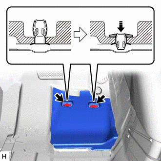
Install the No. 1 dash panel insulator pad with 2 new clips as shown in the illustration.
-
Install the front floor carpet assembly to its original position.
-
Install the cowl side trim board LH.
-
Install the front door scuff plate LH.
-