BRAKE ACTUATOR(for LHD) INSTALLATION
PROCEDURE
-
INSTALL BRAKE ACTUATOR ASSEMBLY
-
Install the brake actuator assembly to the brake actuator bracket assembly with the 3 bolts.
- Torque:
- 5.4 N*m { 55 kgf*cm, 48 in.*lbf }
Note
-
Do not remove the hole plugs of a new brake actuator assembly before connecting the brake lines because the brake actuator assembly is filled with brake fluid.
-
Do not hold the brake actuator assembly by the connector.
-
Do not apply excessive force to the brake lines.
-
Be careful not to allow any brake fluid to enter the connector.
-
Do not drop the brake actuator assembly when carrying it.
-
-
INSTALL BRAKE BOOSTER PUMP ASSEMBLY
-
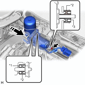
*1 Brake Booster Pump Collar *2 Brake Booster Pump Bushing *3 Brake Actuator Case Collar 
Install in this Direction Install the brake booster pump assembly to the brake actuator bracket assembly with the nut.
- Torque:
- 5.4 N*m { 55 kgf*cm, 48 in.*lbf }
Note
-
Be careful not to allow any brake fluid to enter the connector.
-
When installing the brake booster pump assembly to the brake actuator bracket assembly, confirm that the brake booster pump bushing and brake actuator case collar are on the brake actuator bracket assembly, and 2 brake booster pump bushings and 2 brake booster pump collars are on the brake booster pump assembly.
-
Do not drop the brake booster pump assembly when carrying it.
-
Engage the claw and clamp to install the brake booster pump assembly wire harness to the brake actuator bracket assembly.
-
-
INSTALL ACCUMULATOR TO BRAKE MASTER CYLINDER TUBE
-
Temporarily tighten the accumulator to brake master cylinder tube to the brake booster pump assembly.
-
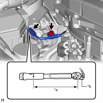
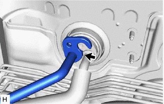
*a Torque Wrench Fulcrum Length *b Union Nut Wrench Install the accumulator to brake master cylinder tube with the bolt.
- Torque:
- 7.0 N*m { 71 kgf*cm, 62 in.*lbf }
-
Using a union nut wrench, tighten the accumulator to brake master cylinder tube.
- Torque:
- Specified tightening torque
- 15.2 N*m { 155 kgf*cm, 11 ft.*lbf }
Note
-
Do not kink or damage the accumulator to brake master cylinder tube.
-
Do not allow the accumulator to brake master cylinder tube to twist or interfere with other parts or the vehicle body during tightening.
-
Do not allow any foreign matter such as dirt or dust to enter the accumulator to brake master cylinder tube from the connecting parts.
Tech Tips
-
Calculate the torque wrench reading when changing the fulcrum length of the torque wrench.
-
When using a union nut wrench (fulcrum length of 22 mm (0.866 in.)) + torque wrench (fulcrum length of 162 mm (6.38 in.)):
13.38 N*m (136 kgf*cm, 10 ft.*lbf)
-
-
CONNECT BRAKE LINE
-
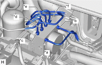
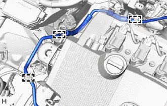
*a From 1st Chamber of Brake Booster with Master Cylinder Assembly *b From 2nd Chamber of Brake Booster with Master Cylinder Assembly *c To Front Wheel Cylinder Assembly LH *d To Rear Wheel Cylinder Assembly RH *e To Rear Wheel Cylinder Assembly LH *f To Front Wheel Cylinder Assembly RH Temporarily tighten the 6 brake lines to the correct positions on the brake actuator assembly as shown in the illustration.
-
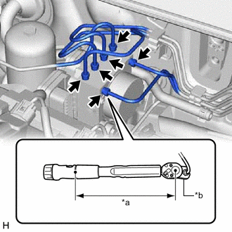
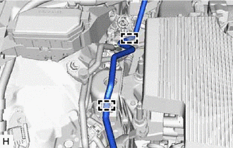
*a Torque Wrench Fulcrum Length *b Union Nut Wrench Using a union nut wrench, fully tighten the 6 brake lines.
- Torque:
- Specified tightening torque
- 15.2 N*m { 155 kgf*cm, 11 ft.*lbf }
Note
-
Do not kink or damage the brake lines.
-
Do not allow the brake lines to twist or interfere with other parts or the vehicle body during tightening.
-
Do not allow any foreign matter such as dirt or dust to enter the brake lines from the connecting parts.
Tech Tips
-
Calculate the torque wrench reading when changing the fulcrum length of the torque wrench.
-
When using a union nut wrench (fulcrum length of 22 mm (0.866 in.)) + torque wrench (fulcrum length of 162 mm (6.38 in.)):
13.38 N*m (136 kgf*cm, 10 ft.*lbf)
-
-
INSTALL NO. 1 BRAKE ACTUATOR HOSE
-
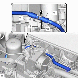
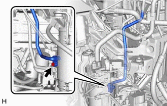
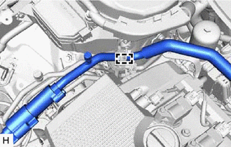
*1 Brake Actuator Hose Clamp *a Protector *b Identification Mark *c Contacts Install the No. 1 brake actuator hose to the brake actuator hose clamp.
Note
-
Make sure to install the No. 1 brake actuator hose so that the protector on the brake booster pump assembly side contacts the brake actuator hose clamp.
-
Make sure to install the No. 1 brake actuator hose so that its identification mark can be seen.
-
-
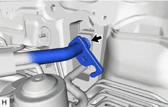
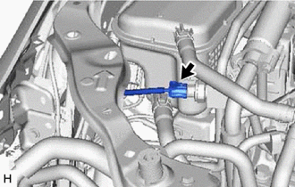
*a Identification Mark 
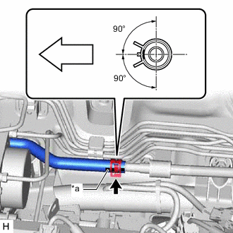
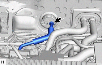
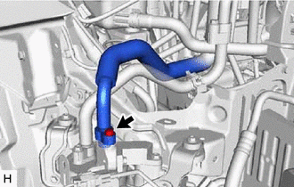
Front of the vehicle Connect the No. 1 brake actuator hose to the No. 1 brake actuator tube to install it, and slide the clip to secure it.
Note
-
Make sure to connect the No. 1 brake actuator hose with its identification mark facing the front of the vehicle.
-
Install the clip within the range shown in the illustration.
-
-
-
CONNECT ENGINE ROOM MAIN WIRE
-
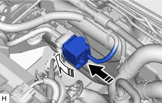
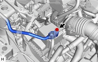
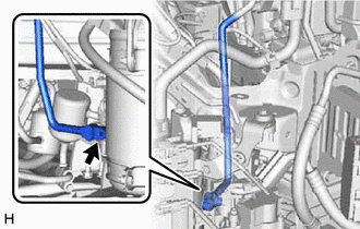
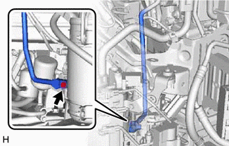
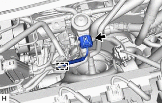
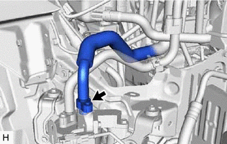
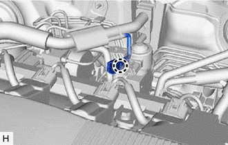
Connect the connector 
Lock the lock lever Connect the connector to the brake booster pump assembly and lock the lock lever as shown in the illustration.
Note
-
Make sure that the connector is locked securely.
-
Make sure that the connector can be connected smoothly. Do not allow water, oil or dirt to enter the connector.
-
-
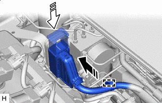
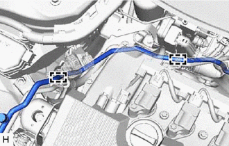
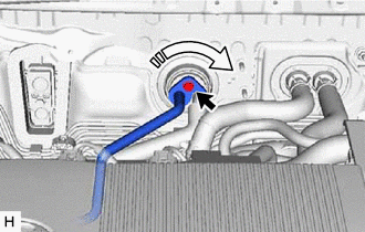
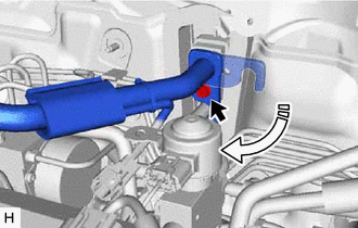
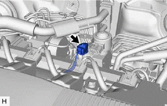
Connect the connector Lock the lock lever Connect the connector to the brake actuator assembly and lock the lock lever as shown in the illustration.
Note
-
Make sure that the connector is locked securely.
-
Make sure that the connector can be connected smoothly. Do not allow water, oil or dirt to enter the connector.
-
-
Engage the clamp to install the engine room main wire.
-
-
INSTALL NO. 2 DISCHARGE HOSE SUB-ASSEMBLY
-
Remove the vinyl tape from the No. 2 discharge hose sub-assembly.
-
Sufficiently apply compressor oil to a new O-ring and the fitting surface of the discharge hose sub-assembly.
Compressor Oil ND-OIL 11 or equivalent -
Install the O-ring to the discharge hose sub-assembly.
Note
Keep the O-ring and O-ring fitting surface free of foreign matter.
-
Sufficiently apply compressor oil to a new O-ring and the fitting surface of the No. 2 discharge hose sub-assembly.
Compressor Oil ND-OIL 11 or equivalent -
Install the O-ring to the No. 2 discharge hose sub-assembly.
Note
Keep the O-ring and O-ring fitting surface free of foreign matter.
-
Engage the 3 clamps to install the No. 2 discharge hose sub-assembly.
-
Connect the No. 2 discharge hose sub-assembly to the air conditioning unit assembly.
-
Connect the No. 2 discharge hose sub-assembly to the discharge hose sub-assembly with the bolt.
- Torque:
- 9.8 N*m { 100 kgf*cm, 87 in.*lbf }
-
-
INSTALL DISCHARGE TUBE SUB-ASSEMBLY
-
Remove the vinyl tape from the discharge tube sub-assembly.
-
Sufficiently apply compressor oil to 2 new O-rings and the fitting surface of the discharge tube sub-assembly.
Compressor Oil ND-OIL 11 or equivalent -
Install the 2 O-rings to the discharge tube sub-assembly.
Note
Keep the O-rings and O-ring fitting surfaces free of foreign matter.
-
Engage the 2 clamps to install the discharge tube sub-assembly.
-
Connect the discharge tube sub-assembly to the air conditioning unit assembly.
-
Connect the discharge tube sub-assembly to the accumulator and accessory assembly.
-
Rotate the hook connector as shown in the illustration.
-
Insert the hose joint into the fitting hole securely and install the bolt.
- Torque:
- 9.8 N*m { 100 kgf*cm, 87 in.*lbf }
-
Install the bolt.
- Torque:
- 9.8 N*m { 100 kgf*cm, 87 in.*lbf }
-
-
INSTALL DISCHARGE PIPE SUB-ASSEMBLY
-
Remove the vinyl tape from the discharge pipe sub-assembly.
-
Sufficiently apply compressor oil to 2 new O-rings and the fitting surface of the discharge pipe sub-assembly.
Compressor Oil ND-OIL 11 or equivalent -
Install the 2 O-rings to the discharge pipe sub-assembly.
Note
Keep the O-rings and O-ring fitting surfaces free of foreign matter.
-
Engage the 2 clamps to install the discharge pipe sub-assembly.
-
Connect the discharge pipe sub-assembly to the air conditioning unit assembly.
-
Connect the discharge pipe sub-assembly to the accumulator and accessory assembly with the bolt.
- Torque:
- 9.8 N*m { 100 kgf*cm, 87 in.*lbf }
-
Engage the clamp and connect the connector.
-
-
INSTALL SUCTION TUBE SUB-ASSEMBLY
-
Remove the vinyl tape from the suction tube sub-assembly.
-
Sufficiently apply compressor oil to 2 new O-rings and the fitting surface of the suction tube sub-assembly.
Compressor Oil ND-OIL 11 or equivalent -
Install the 2 O-rings to the suction tube sub-assembly.
Note
Keep the O-rings and O-ring fitting surfaces free of foreign matter.
-
Engage the clamp to install the suction tube sub-assembly.
-
Connect the suction tube sub-assembly to the air conditioning unit assembly.
-
Connect the suction tube sub-assembly to the accumulator and accessory assembly.
-
Rotate the hook connector as shown in the illustration.
-
Insert the hose joint into the fitting hole securely and install the bolt.
- Torque:
- 9.8 N*m { 100 kgf*cm, 87 in.*lbf }
-
Install the bolt.
- Torque:
- 9.8 N*m { 100 kgf*cm, 87 in.*lbf }
-
Engage the claw to install the connector.
-
Connect the connector.
-
-
INSTALL RESERVE TANK
-
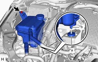
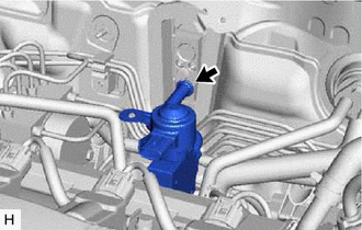
*a Grommet *b Protrusion Fit the protrusion of the reserve tank into the grommet as shown in the illustration.
-
Install the reserve tank with the bolt.
- Torque:
- 5.0 N*m { 51 kgf*cm, 44 in.*lbf }
-
Connect the connector.
-
-
INSTALL HEADLIGHT ASSEMBLY RH
-
BLEED NO. 1 BRAKE ACTUATOR TUBE
-
FILL RESERVOIR WITH BRAKE FLUID
-
CONNECT CABLE TO NEGATIVE AUXILIARY BATTERY TERMINAL
-
BLEED BRAKE SYSTEM
-
CHARGE AIR CONDITIONING SYSTEM WITH REFRIGERANT
for HFC-134a (R134a): Click here
for HFO-1234yf (R1234yf): Click here
-
WARM UP COMPRESSOR
for HFC-134a (R134a): Click here
for HFO-1234yf (R1234yf): Click here
-
INSPECT FOR REFRIGERANT LEAK
for HFC-134a (R134a): Click here
for HFO-1234yf (R1234yf): Click here
-
INSTALL OUTER COWL TOP PANEL SUB-ASSEMBLY
-
INSTALL COWL BODY MOUNTING REINFORCEMENT LH
-
INSTALL WATER GUARD PLATE
-
INSTALL NO. 1 HEATER AIR DUCT SPLASH SHIELD SEAL
-
INSTALL WINDSHIELD WIPER MOTOR AND LINK ASSEMBLY