BRAKE ACTUATOR(for LHD) REMOVAL
CAUTION / NOTICE / HINT
The necessary procedures (adjustment, calibration, initialization, or registration) that must be performed after parts are removed, installed, or replaced during brake actuator assembly removal/installation are shown below.
| Replaced Part or Performed Procedure | Necessary Procedure | Effect/Inoperative Function when Necessary Procedure not Performed | Link |
|---|---|---|---|
| Auxiliary battery terminal is disconnected/reconnected | Memorize steering angle neutral point | Lane departure alert system (w/ Steering control) | |
| Intelligent clearance sonar system | |||
| Simple intelligent parking assist system | |||
| Pre-crash safety system | |||
| Adaptive high beam system | |||
| Parking assist monitor system | |||
| Initialize back door lock | Power door lock control system | ||
| Replacement of brake actuator assembly |
|
|
Click here for Initialization Click here for Calibration |
| Removal/installation of the front bumper assembly |
|
|
CAUTION / NOTICE / HINT
Note
While the auxiliary battery is connected, even if the power switch is off, the brake control system activates when the brake pedal is depressed or any door courtesy switch turns on. Therefore, when servicing the brake system components, do not operate the brake pedal or open/close the doors while the auxiliary battery is connected.
PROCEDURE
-
PRECAUTION
Note
After turning the power switch off, waiting time may be required before disconnecting the cable from the negative (-) auxiliary battery terminal. Therefore, make sure to read the disconnecting the cable from the negative (-) auxiliary battery terminal notices before proceeding with work.
-
RECOVER REFRIGERANT FROM REFRIGERATION SYSTEM
for HFC-134a (R134a): Click here
for HFO-1234yf (R1234yf): Click here
-
REMOVE WINDSHIELD WIPER MOTOR AND LINK ASSEMBLY
-
REMOVE NO. 1 HEATER AIR DUCT SPLASH SHIELD SEAL
-
REMOVE WATER GUARD PLATE
-
REMOVE COWL BODY MOUNTING REINFORCEMENT LH
-
REMOVE OUTER COWL TOP PANEL SUB-ASSEMBLY
-
PERFORM ACCUMULATOR PRESSURE ZERO DOWN
-
DRAIN BRAKE FLUID
Note
If brake fluid leaks onto any painted surface, immediately wash it off.
-
REMOVE HEADLIGHT ASSEMBLY RH
-
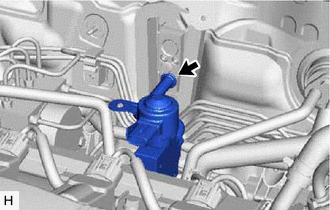
SEPARATE RESERVE TANK
-
Disconnect the connector.
-
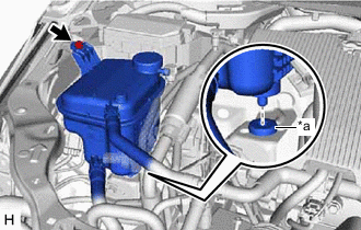
*a Grommet Remove the bolt and separate the reserve tank.
Note
Make sure the grommet remains attached to the vehicle body.
-
-
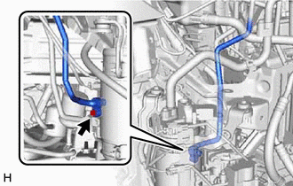
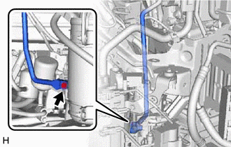
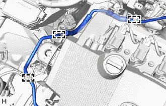
REMOVE SUCTION TUBE SUB-ASSEMBLY
-
Disconnect the connector.
-
Disengage the claw and separate the connector.
-
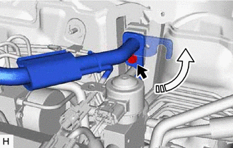
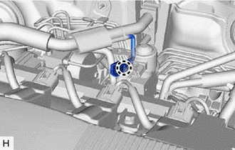
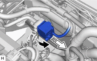
Remove the bolt and rotate the hook connector as shown in the illustration.
-
Disconnect the suction tube sub-assembly from the air conditioning unit assembly.
-
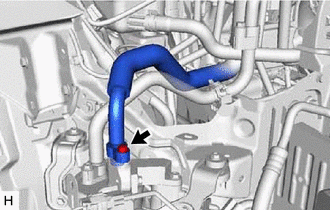
Remove the bolt and disconnect the suction tube sub-assembly from the accumulator and accessory assembly.
-
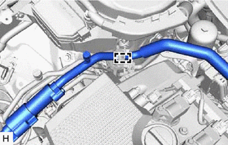
Disengage the clamp to remove the suction tube sub-assembly.
-
Remove the 2 O-rings from the suction tube sub-assembly.
Note
Seal the openings of the disconnected parts using vinyl tape to prevent entry of moisture and foreign matter.
-
-
REMOVE DISCHARGE PIPE SUB-ASSEMBLY
-
Disconnect the connector and disengage the clamp.
-
Remove the bolt and disconnect the discharge pipe sub-assembly from the accumulator and accessory assembly.
-
Disconnect the discharge pipe sub-assembly from the air conditioning unit assembly.
-
Disengage the 2 clamps to remove the discharge pipe sub-assembly.
-
Remove the 2 O-rings from the discharge pipe sub-assembly.
Note
Seal the openings of the disconnected parts using vinyl tape to prevent entry of moisture and foreign matter.
-
-
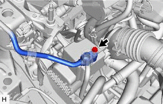
REMOVE DISCHARGE TUBE SUB-ASSEMBLY
-
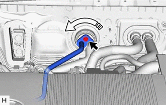
Remove the bolt and rotate the hook connector as shown in the illustration.
-
Disconnect the discharge tube sub-assembly from the air conditioning unit assembly.
-
Remove the bolt and disconnect the discharge tube sub-assembly from the accumulator and accessory assembly.
-
Disengage the 2 clamps to remove the discharge tube sub-assembly.
-
Remove the 2 O-rings from the discharge tube sub-assembly.
Note
Seal the openings of the disconnected parts using vinyl tape to prevent entry of moisture and foreign matter.
-
-
REMOVE NO. 2 DISCHARGE HOSE SUB-ASSEMBLY
-
Remove the bolt and disconnect the No. 2 discharge hose sub-assembly from the discharge hose sub-assembly.
-
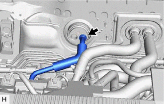
Disconnect the No. 2 discharge hose sub-assembly from the air conditioning unit assembly.
-
Disengage the 3 clamps to remove the No. 2 discharge hose sub-assembly.
-
Remove the O-ring from the No. 2 discharge hose sub-assembly.
Note
Seal the openings of the disconnected parts using vinyl tape to prevent entry of moisture and foreign matter.
-
Remove the O-ring from the discharge hose sub-assembly.
Note
Seal the openings of the disconnected parts using vinyl tape to prevent entry of moisture and foreign matter.
-
-
DISCONNECT ENGINE ROOM MAIN WIRE
-

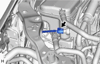
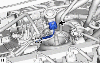
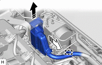
Release the lock lever 
Disconnect the connector Release the lock lever and disconnect the connector from the brake booster pump assembly as shown in the illustration.
Note
Be careful not to allow any brake fluid to enter the connector.
-
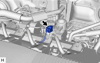
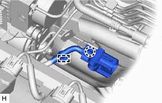
Release the lock lever Disconnect the connector Release the lock lever and disconnect the connector from the brake actuator assembly as shown in the illustration.
Note
Be careful not to allow any brake fluid to enter the connector.
-
Disengage the clamp and separate the engine room main wire.
-
-
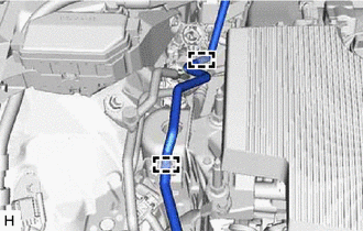
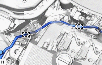
SEPARATE NO. 1 BRAKE ACTUATOR HOSE
-
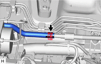
Slide the clip and disconnect the No. 1 brake actuator hose from the No. 1 brake actuator tube.
-
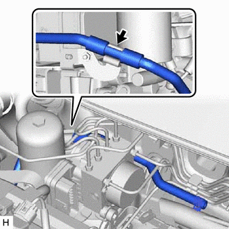
Separate the No. 1 brake actuator hose from the brake actuator hose clamp.
-
-
SEPARATE BRAKE LINE
-
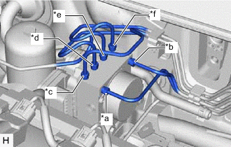
*a From 1st Chamber of Brake Booster with Master Cylinder Assembly *b From 2nd Chamber of Brake Booster with Master Cylinder Assembly *c To Front Wheel Cylinder Assembly LH *d To Rear Wheel Cylinder Assembly RH *e To Rear Wheel Cylinder Assembly LH *f To Front Wheel Cylinder Assembly RH Use tags or make a memo to identify the places to reconnect the brake lines.
-
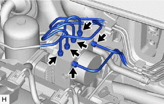
Using a union nut wrench, disconnect the 6 brake lines from the brake actuator assembly.
-
-
SEPARATE ACCUMULATOR TO BRAKE MASTER CYLINDER TUBE
-
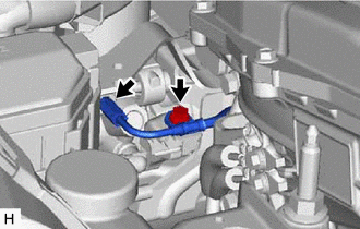
Using a union nut wrench, disconnect the accumulator to brake master cylinder tube from the brake booster pump assembly.
-
Remove the bolt to separate the accumulator to brake master cylinder tube.
-
-
SEPARATE BRAKE BOOSTER PUMP ASSEMBLY
-
Disengage the claw and clamp to separate the brake booster pump assembly wire harness from the brake actuator bracket assembly.
-
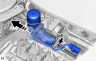
Move in this Direction Remove the nut to separate the brake booster pump assembly from the brake actuator bracket assembly.
Tech Tips
Move the brake booster pump assembly to the position where the lower bolt of the brake actuator assembly can be removed.
-
-
REMOVE BRAKE ACTUATOR ASSEMBLY
-
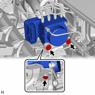
Remove the 3 bolts and brake actuator assembly from the brake actuator bracket assembly.
Note
-
Do not hold the brake actuator assembly by the connector.
-
Do not apply excessive force to the brake lines.
-
Be careful not to allow any brake fluid to enter the connector.
-
Do not drop the brake actuator assembly when carrying it.
-
-