ELECTRONICALLY CONTROLLED BRAKE SYSTEM, Diagnostic DTC:C1428
| DTC Code | DTC Name |
|---|---|
| C1428 | Motor Circuit |
DESCRIPTION
| DTC No. | Detection Item | INF Code | DTC Detection Condition | Trouble Area | Note |
|---|---|---|---|---|---|
| C1428 | Motor Circuit | 611 1160 |
|
Brake actuator assembly | ABS DTC |
CAUTION / NOTICE / HINT
Note
After replacing the brake actuator assembly, perform linear solenoid valve offset learning, ABS holding solenoid valve learning, yaw rate and acceleration sensor zero point calibration and system information memorization after performing "Reset Memory".
PROCEDURE
-
CHECK HARNESS AND CONNECTOR (BRAKE BOOSTER WITH MASTER CYLINDER ASSEMBLY - BRAKE ACTUATOR ASSEMBLY)
-
Make sure that there is no looseness at the locking part and the connecting part of the connectors.
OK The connector is securely connected. -
Disconnect the A32 skid control ECU (brake booster with master cylinder assembly) connector.
-
Disconnect the A33 brake actuator assembly connector (for LHD).
-
Disconnect the A34 brake actuator assembly connector (for RHD).
-
Check both the connector case and the terminals for deformation and corrosion.
OK No deformation or corrosion. -
Measure the resistance according to the value(s) in the table below.
Standard Resistance for LHD Tester Connection Condition Specified Condition A32-40 (+BM) - A33-13 (+BM) Always Below 1 Ω A32-40 (+BM) or A33-13 (+BM) - Body ground Always 10 kΩ or higher for RHD Tester Connection Condition Specified Condition A32-40 (+BM) - A34-13 (+BM) Always Below 1 Ω A32-40 (+BM) or A34-13 (+BM) - Body ground Always 10 kΩ or higher Result Proceed to OK NG
NG 
REPAIR OR REPLACE HARNESS OR CONNECTOR
OK 
-
-
CHECK HARNESS AND CONNECTOR (GND TERMINAL)
-
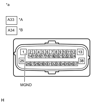
*A for LHD *B for RHD *a Front view of wire harness connector
(to Brake Actuator Assembly)
Measure the resistance according to the value(s) in the table below.
Standard Resistance for LHD Tester Connection Condition Specified Condition A33-1 (MGND) - Body ground Always Below 1 Ω for RHD Tester Connection Condition Specified Condition A34-1 (MGND) - Body ground Always Below 1 Ω Result Proceed to OK NG
OK
REPLACE BRAKE ACTUATOR ASSEMBLY for LHD: Click here
REPLACE BRAKE ACTUATOR ASSEMBLY for RHD: Click hereNG
REPAIR OR REPLACE HARNESS OR CONNECTOR (GND CIRCUIT)
-