ELECTRONICALLY CONTROLLED BRAKE SYSTEM, Diagnostic DTC:C1427
| DTC Code | DTC Name |
|---|---|
| C1427 | Malfunction in Motor |
DESCRIPTION
When the power switch is on (READY), the stop light switch assembly off and the vehicle speed is 20 km/h (12 mph) or more, the skid control ECU (brake booster with master cylinder assembly) performs a self-diagnosis of the ABS motor relay circuit during the initial check of the actuator.
| DTC No. | Detection Item | INF Code | DTC Detection Condition | Trouble Area | Note |
|---|---|---|---|---|---|
| C1427 | Malfunction in Motor | 1159 | The pump motor built into the brake actuator assembly is not operating correctly. |
|
Electronically controlled brake system DTC |
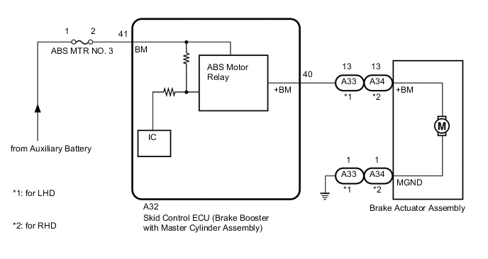
WIRING DIAGRAM
CAUTION / NOTICE / HINT
Note
-
After replacing the skid control ECU (brake booster with master cylinder assembly) or brake actuator assembly, perform linear solenoid valve offset learning, ABS holding solenoid valve learning, yaw rate and acceleration sensor zero point calibration and system information memorization after performing "Reset Memory".
-
Inspect the fuses for circuits related to this system before performing the following procedure.
PROCEDURE
-
PERFORM ACTIVE TEST USING GTS (ABS MOTOR RELAY)
-
Select the Active Test on the GTS.
Chassis > ABS/VSC/TRC > Active TestTester Display Measurement Item Control Range Diagnostic Note Motor Relay ABS motor relay Relay ON/OFF Operating sound of motor can be heard.
Chassis > ABS/VSC/TRC > Active TestTester Display Motor Relay -
Check the operating sound of the ABS motor relay when operating it with the GTS.
Result Result Proceed to The operating sound is heard. A The operating sound is not heard. B
B 
CHECK HARNESS AND CONNECTOR (BRAKE BOOSTER WITH MASTER CYLINDER ASSEMBLY - BRAKE ACTUATOR ASSEMBLY) Click here
A 
-
-
RECONFIRM DTC
-
Clear the DTCs.
Chassis > ABS/VSC/TRC > Clear DTCs -
Turn the power switch off.
-
Turn the power switch on (READY).
-
Perform a road test.
-
Check if the same DTC is output.
Chassis > ABS/VSC/TRC > Trouble CodesResult Result Proceed to DTC C1427 is not output. A DTC C1427 is output. B
A 
USE SIMULATION METHOD TO CHECK Click here
B
REPLACE BRAKE BOOSTER WITH MASTER CYLINDER ASSEMBLY for LHD: Click here
REPLACE BRAKE BOOSTER WITH MASTER CYLINDER ASSEMBLY for RHD: Click here -
-
CHECK HARNESS AND CONNECTOR (BRAKE BOOSTER WITH MASTER CYLINDER ASSEMBLY - BRAKE ACTUATOR ASSEMBLY)
-
Turn the power switch off.
-
Make sure that there is no looseness at the locking part and the connecting part of the connectors.
OK The connector is securely connected. -
Disconnect the A32 skid control ECU (brake booster with master cylinder assembly) connector.
-
Disconnect the A33 brake actuator assembly connector (for LHD).
-
Disconnect the A34 brake actuator assembly connector (for RHD).
-
Check both the connector case and the terminals for deformation and corrosion.
OK No deformation or corrosion. -
Measure the resistance according to the value(s) in the table below.
Standard Resistance for LHD Tester Connection Condition Specified Condition A32-40 (+BM) - A33-13 (+BM) Always Below 1 Ω A32-40 (+BM) or A33-13 (+BM) - Body ground Always 10 kΩ or higher for RHD Tester Connection Condition Specified Condition A32-40 (+BM) - A34-13 (+BM) Always Below 1 Ω A32-40 (+BM) or A34-13 (+BM) - Body ground Always 10 kΩ or higher Result Proceed to OK NG
NG
REPAIR OR REPLACE HARNESS OR CONNECTOR
OK
-
-
CHECK HARNESS AND CONNECTOR (GND TERMINAL)
-
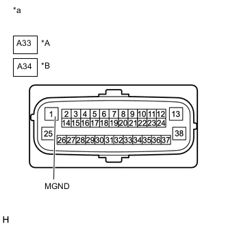
*A for LHD *B for RHD *a Front view of wire harness connector
(to Brake Actuator Assembly)
Measure the resistance according to the value(s) in the table below.
Standard Resistance for LHD Tester Connection Condition Specified Condition A33-1 (MGND) - Body ground Always Below 1 Ω for RHD Tester Connection Condition Specified Condition A34-1 (MGND) - Body ground Always Below 1 Ω Result Proceed to OK NG
NG
REPAIR OR REPLACE HARNESS OR CONNECTOR (GND CIRCUIT)
OK
-
-
RECONFIRM DTC
-
Reconnect the A32 skid control ECU (brake booster with master cylinder assembly) connector.
-
Reconnect the A33 brake actuator assembly connector (for LHD).
-
Reconnect the A34 brake actuator assembly connector (for RHD).
-
Clear the DTCs.
Chassis > ABS/VSC/TRC > Clear DTCs -
Turn the power switch off.
-
Turn the power switch on (READY).
-
Perform a road test.
-
Check if the same DTC is output.
Chassis > ABS/VSC/TRC > Trouble CodesResult Result Proceed to DTC C1427 is not output. A DTC C1427 is output. B
A
USE SIMULATION METHOD TO CHECK Click here
B
REPLACE BRAKE ACTUATOR ASSEMBLY for LHD: Click here
REPLACE BRAKE ACTUATOR ASSEMBLY for RHD: Click here -