ELECTRONICALLY CONTROLLED BRAKE SYSTEM, Diagnostic DTC:C1417
| DTC Code | DTC Name |
|---|---|
| C1417 | IG1 Voltage Supply too High |
DESCRIPTION
If a malfunction is detected in the power source circuit, the skid control ECU (brake booster with master cylinder assembly) stores DTC C1417 and prohibits operation of ABS, brake assist, regenerative brake cooperative control, etc.
DTC C1417 is stored if an excessive ECU voltage due to a malfunction in the auxiliary battery, charging circuit, etc. is detected, and is cleared when the ECU voltage returns to normal.
| DTC No. | Detection Item | INF Code | DTC Detection Condition | Trouble Area | Note |
|---|---|---|---|---|---|
| C1417 | IG1 Voltage Supply too High | 553 | The internal voltage of the skid control ECU (brake booster with master cylinder assembly) is 16.44 V or more for 0.8 seconds or more. |
|
Electronically controlled brake system DTC |
CAUTION / NOTICE / HINT
Note
-
After replacing the skid control ECU (brake booster with master cylinder assembly), perform linear solenoid valve offset learning, ABS holding solenoid valve learning, yaw rate and acceleration sensor zero point calibration and system information memorization after performing "Reset Memory".
-
Inspect the fuses for circuits related to this system before performing the following procedure.
PROCEDURE
-
CHECK AUXILIARY BATTERY
-
Check the auxiliary battery voltage.
Standard Voltage Tester Connection Condition Specified Condition Auxiliary battery Power switch on (IG) 11 to 14 V Auxiliary battery Power switch on (READY) 11 to 15.5 V Result Proceed to OK NG
NG 
CHARGE OR REPLACE AUXILIARY BATTERY
OK 
-
-
CHECK HARNESS AND CONNECTOR (POWER SOURCE TERMINAL)
-
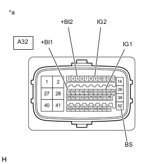
*a Front view of wire harness connector
(to Skid Control ECU (Brake Booster with Master Cylinder Assembly))
Turn the power switch off.
-
Make sure that there is no looseness at the locking part and the connecting part of the connector.
OK The connector is securely connected. -
Disconnect the A32 skid control ECU (brake booster with master cylinder assembly) connector.
-
Check both the connector case and the terminals for deformation and corrosion.
OK No deformation or corrosion. -
Measure the voltage according to the value(s) in the table below.
Standard Voltage Tester Connection Condition Specified Condition A32-15 (+BI1) - Body ground Always 11 to 14 V A32-5 (+BI2) - Body ground Always 11 to 14 V A32-52 (BS) - Body ground Always 11 to 14 V A32-23 (IG1) - Body ground Power switch on (IG) 11 to 14 V A32-9 (IG2) - Body ground Power switch on (IG) 11 to 14 V Result Proceed to OK NG
NG
REPAIR OR REPLACE HARNESS OR CONNECTOR (POWER SOURCE CIRCUIT)
OK
-
-
RECONFIRM DTC
-
Turn the power switch off.
-
Reconnect the A32 skid control ECU (brake booster with master cylinder assembly) connector.
-
Clear the DTCs.
Chassis > ABS/VSC/TRC > Clear DTCs -
Turn the power switch off.
-
Turn the power switch on (READY).
-
Perform a road test.
-
Check if the same DTC is output.
Chassis > ABS/VSC/TRC > Trouble CodesResult Result Proceed to DTC C1417 is not output. A DTC C1417 is output. B
A
USE SIMULATION METHOD TO CHECK Click here
B
REPLACE BRAKE BOOSTER WITH MASTER CYLINDER ASSEMBLY for LHD: Click here
REPLACE BRAKE BOOSTER WITH MASTER CYLINDER ASSEMBLY for RHD: Click here -