ELECTRONICALLY CONTROLLED BRAKE SYSTEM TERMINALS OF ECU
-
TERMINALS OF ECU
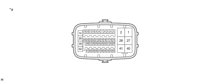
*a Component without harness connected
(Skid Control ECU (Brake Booster with Master Cylinder Assembly))
- - Terminal No. (Symbol) Terminal Description 1 (MRO1) Motor power supply output 1 2 (MRI1) Motor power supply input 1 3 (FR+) Front speed sensor RH (+) power supply output 4 (FR-) Front speed sensor RH (-) signal input 5 (+BI2) +BI2 power source input 6 - (Not used) 7 (RR+) Rear speed sensor RH (+) power supply output 8 (RR-) Rear speed sensor RH (-) signal input 9 (IG2) IG2 power source input 10 - (Not used) 11 (SP1) Speed sensor signal output 12 (STP) Stop light switch assembly input 13 (SKG1) Brake pedal stroke sensor assembly ground 1 14 (+BS) ABS solenoid drive power output 15 (+BI1) +BI1 power source input 16 (LBL) Brake fluid level warning switch (Brake booster with master cylinder assembly) input 17 (SKS1) Brake pedal stroke sensor assembly signal input 1 18 (CSW) VSC OFF switch (Combination switch assembly) input 19 (SKS2) Brake pedal stroke sensor assembly signal input 2 20 - (Not used) 21 (VSK2) Brake pedal stroke sensor assembly power supply output 2 22 (STPO)* Stop light control relay (Stop light switch assembly) output 23 (IG1) IG1 power source input 24 (CTY) Front door courtesy light switch assembly input (for driver side) 25 (VSK1) Brake pedal stroke sensor assembly power supply output 1 26 (GND1) Skid control ECU (Brake booster with master cylinder assembly) ground 1 27 (MRO2) Motor power supply output 2 28 (MRI2) Motor power supply input 2 29 (CA2L) CAN communication line 2 (L) 30 (CA2H) CAN communication line 2 (H) 31 (FL+) Front speed sensor LH (+) power supply output 32 (FL-) Front speed sensor LH (-) signal input 33 (SKG2) Brake pedal stroke sensor assembly ground 2 34 (RL+) Rear speed sensor LH (+) power supply output 35 (RL-) Rear speed sensor LH (-) signal input 36 - (Not used) 37 (STP2)* Stop light control relay (Stop light switch assembly) input 38 - (Not used) 39 (GND2) Skid control ECU (Brake booster with master cylinder assembly) ground 2 40 (+BM) ABS motor drive power output 41 (BM) ABS motor relay power supply input 42 (CA1L) CAN communication line 1 (L) 43 (CA1H) CAN communication line 1 (H) 44 (SFRR) Front ABS reduction solenoid RH (-) output 45 (SFLR) Front ABS reduction solenoid LH (-) output 46 (SRRR) Rear ABS reduction solenoid RH (-) output 47 (SRLR) Rear ABS reduction solenoid LH (-) output 48 (SFRH) Front ABS holding solenoid RH (-) output 49 (SFLH) Front ABS holding solenoid LH (-) output 50 (SRRH) Rear ABS holding solenoid RH (-) output 51 (SRLH) Rear ABS holding solenoid LH (-) output 52 (BS) ABS solenoid relay power supply input *: w/o Canister Pump Module
-
TERMINAL INSPECTION
-
Disconnect the connector and measure the voltage or resistance on the wire harness side.
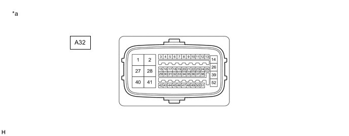
*a Front view of wire harness connector
(to Skid Control ECU (Brake Booster with Master Cylinder Assembly))
- - Tech Tips
The voltage cannot be measured with the connector connected to the skid control ECU (brake booster with master cylinder assembly) as the connector is watertight.
Standard Terminal No. (Symbol) Wiring Color Terminal Description Condition Specified Condition A32-2 (MRI1) - Body ground W - Body ground Motor power supply input 1 Always 11 to 14 V A32-5 (+BI2) - Body ground B - Body ground +BI2 power source input Always 11 to 14 V A32-9 (IG2) - Body ground G - Body ground IG2 power source input Power switch on (IG) 11 to 14 V A32-12 (STP) - Body ground L - Body ground*1
SB - Body ground*2
Stop light switch assembly input Stop light switch assembly on → off
(Brake pedal depressed → released)
11 to 14 V → Below 1.5 V A32-15 (+BI1) - Body ground V - Body ground +BI1 power source input Always 11 to 14 V A32-16 (LBL) - Body ground GR - Body ground Brake fluid level warning switch (Brake booster with master cylinder assembly) input Brake fluid level warning switch off → on 1.84 to 2.16 kΩ → Below 1 Ω A32-18 (CSW) - Body ground G - Body ground VSC OFF switch (Combination switch assembly) input VSC OFF switch held on → off (Released) Below 1 Ω → 10 kΩ or higher A32-22 (STPO) - Body ground*1 BE - Body ground Stop light control relay (Stop light switch assembly) output Always 11 to 14 V A32-23 (IG1) - Body ground B - Body ground IG1 power source input Power switch on (IG) 11 to 14 V A32-24 (CTY) - Body ground BR - Body ground Front door courtesy light switch assembly input (for driver side) Driver door closed → open 11 to 14 V → Below 1.5 V A32-26 (GND1) - Body ground W-B - Body ground Skid control ECU (Brake booster with master cylinder assembly) ground 1 Always Below 1 Ω A32-28 (MRI2) - Body ground R - Body ground Motor power supply input 2 Always 11 to 14 V A32-37 (STP2) - Body ground*1 SB - Body ground Stop light control relay (Stop light switch assembly) input Stop light switch assembly on → off
(Brake pedal depressed → released)
11 to 14 V → Below 1.5 V A32-39 (GND2) - Body ground W-B - Body ground Skid control ECU (Brake booster with master cylinder assembly) ground 2 Always Below 1 Ω A32-41 (BM) - Body ground G - Body ground ABS motor relay power supply input Always 11 to 14 V A32-52 (BS) - Body ground W - Body ground ABS solenoid relay power supply input Always 11 to 14 V *1: w/o Canister Pump Module
*2: w/ Canister Pump Module
-