ELECTRONICALLY CONTROLLED BRAKE SYSTEM, Diagnostic DTC:C1247, C1392
| DTC Code | DTC Name |
|---|---|
| C1247 | Stroke Sensor |
| C1392 | Zero Point Calibration of Stroke Sensor undone |
DESCRIPTION
The brake pedal stroke sensor assembly sends a signal about the pedal stroke to the skid control ECU (brake booster with master cylinder assembly).
| DTC No. | Detection Item | INF Code | DTC Detection Condition | Trouble Area | Note |
|---|---|---|---|---|---|
| C1247 | Stroke Sensor | 211 212 213 214 215 216 217 |
|
|
Electronically controlled brake system DTC |
| C1392 | Zero Point Calibration of Stroke Sensor undone | 1124 | The brake pedal stroke sensor assembly zero point calibration is not performed. (Normal brake pedal stroke sensor assembly zero point not memorized.) |
Normal brake pedal stroke sensor assembly zero point not memorized. (Linear solenoid valve offset learning is not performed or Test Mode is not performed or not complete.) |
Electronically controlled brake system DTC Tech Tips During test mode, related DTCs are cleared. |
WIRING DIAGRAM
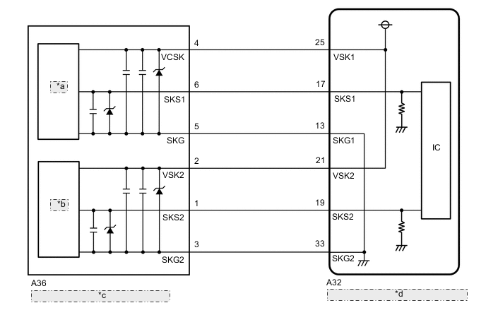
| *a | Hall IC1 |
| *b | Hall IC2 |
| *c | Brake Pedal Stroke Sensor Assembly |
| *d | Skid Control ECU (Brake Booster with Master Cylinder Assembly) |
CAUTION / NOTICE / HINT
Note
After replacing the skid control ECU (brake booster with master cylinder assembly) or brake pedal stroke sensor assembly, perform linear solenoid valve offset learning, ABS holding solenoid valve learning, yaw rate and acceleration sensor zero point calibration and system information memorization after performing "Reset Memory".
PROCEDURE
-
CHECK BRAKE PEDAL
-
Check that the brake pedal and the brake pedal stroke sensor assembly are properly installed and that the pedal can be depressed normally.
-
Check and adjust the brake pedal height.
for LHD: Click here
for RHD: Click here
-
Adjust the brake pedal stroke sensor assembly.
for LHD: Click here
for RHD: Click here
Result Proceed to NEXT
NEXT 
-
-
CHECK HARNESS AND CONNECTOR (BRAKE BOOSTER WITH MASTER CYLINDER ASSEMBLY - BRAKE PEDAL STROKE SENSOR ASSEMBLY)
-
Make sure that there is no looseness at the locking part and the connecting part of the connectors.
OK The connector is securely connected. -
Disconnect the A32 skid control ECU (brake booster with master cylinder assembly) connector.
-
Disconnect the A36 brake pedal stroke sensor assembly connector.
-
Check both the connector case and the terminals for deformation and corrosion.
OK No deformation or corrosion. -
Measure the resistance according to the value(s) in the table below.
Standard Resistance Tester Connection Condition Specified Condition A32-13 (SKG1) - A36-5 (SKG) Always Below 1 Ω A32-13 (SKG1) or A36-5 (SKG) - Body ground Always 10 kΩ or higher A32-17 (SKS1) - A36-6 (SKS1) Always Below 1 Ω A32-17 (SKS1) or A36-6 (SKS1) - Body ground Always 10 kΩ or higher A32-19 (SKS2) - A36-1 (SKS2) Always Below 1 Ω A32-19 (SKS2) or A36-1 (SKS2) - Body ground Always 10 kΩ or higher A32-21 (VSK2) - A36-2 (VSK2) Always Below 1 Ω A32-21 (VSK2) or A36-2 (VSK2) - Body ground Always 10 kΩ or higher A32-25 (VSK1) - A36-4 (VCSK) Always Below 1 Ω A32-25 (VSK1) or A36-4 (VCSK) - Body ground Always 10 kΩ or higher A32-33 (SKG2) - A36-3 (SKG2) Always Below 1 Ω A32-33 (SKG2) or A36-3 (SKG2) - Body ground Always 10 kΩ or higher Result Proceed to OK NG
NG 
REPAIR OR REPLACE HARNESS OR CONNECTOR
OK
-
-
INSPECT BRAKE BOOSTER WITH MASTER CYLINDER ASSEMBLY (SENSOR OUTPUT)
-
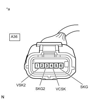
*a Front view of wire harness connector
(to Brake Pedal Stroke Sensor Assembly)
Reconnect the A32 skid control ECU (brake booster with master cylinder assembly) connector.
-
Turn the power switch on (IG).
-
Measure the voltage according to the value(s) in the table below.
Standard Voltage Tester Connection Condition Specified Condition A36-4 (VCSK) - A36-5 (SKG) Power switch on (IG) 4.84 to 5.16 V A36-2 (VSK2) - A36-3 (SKG2) Power switch on (IG) 4.84 to 5.16 V Result Proceed to OK NG
OK
REPLACE BRAKE PEDAL STROKE SENSOR ASSEMBLY for LHD: Click here
REPLACE BRAKE PEDAL STROKE SENSOR ASSEMBLY for RHD: Click hereNG
REPLACE BRAKE BOOSTER WITH MASTER CYLINDER ASSEMBLY for LHD: Click here
REPLACE BRAKE BOOSTER WITH MASTER CYLINDER ASSEMBLY for RHD: Click here -