REAR LOWER ARM INSTALLATION
CAUTION / NOTICE / HINT
Tech Tips
-
Use the same procedure for the RH side and LH side.
-
The following procedure is for the LH side.
PROCEDURE
-
TEMPORARILY INSTALL REAR NO. 1 SUSPENSION ARM ASSEMBLY
-
Temporarily install the rear No. 1 suspension arm assembly to the rear axle carrier sub-assembly and rear suspension member sub-assembly with the 2 bolts and 2 nuts.
Note
-
Because the nut has its own stopper, do not turn the nut. Tighten the bolt with the nut secured.
-
Insert the bolt with the threaded end facing the rear of the vehicle.
-
-
-
TEMPORARILY INSTALL REAR NO. 2 SUSPENSION ARM ASSEMBLY
-
Temporarily install the rear No. 2 suspension arm assembly to the rear suspension member sub-assembly with the No. 2 camber adjust cam, rear suspension toe adjust cam sub-assembly and nut.
Note
-
Insert the rear suspension toe adjust cam sub-assembly from the rear of the vehicle.
-
When tightening the nut, keep the rear suspension toe adjust cam sub-assembly from rotating.
-
-
-
INSTALL REAR LOWER COIL SPRING INSULATOR
-
INSTALL REAR COIL SPRING
-
STABILIZE SUSPENSION
-
INSTALL REAR STABILIZER LINK ASSEMBLY
-
INSTALL REAR NO. 1 SUSPENSION ARM ASSEMBLY
-
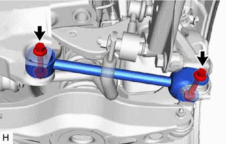
Install the rear No. 1 suspension arm assembly with the 2 bolts.
- Torque:
- 73 N*m { 744 kgf*cm, 54 ft.*lbf }
Note
Because the nut has its own stopper, do not turn the nut. Tighten the bolt with the nut secured.
-
-
INSTALL REAR NO. 2 SUSPENSION ARM ASSEMBLY
-
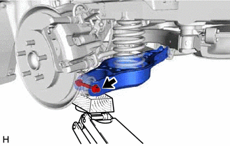
Install the rear No. 2 suspension arm assembly (rear axle carrier sub-assembly side) with the bolt.
- Torque:
- 73 N*m { 744 kgf*cm, 54 ft.*lbf }
Note
Because the nut has its own stopper, do not turn the nut. Tighten the bolt with the nut secured.
-
-
INSTALL REAR HEIGHT CONTROL SENSOR SUB-ASSEMBLY LH (for LH Side)
-
INSTALL REAR FLOOR SIDE MEMBER COVER LH (for LH Side)
w/ Canister Pump Module: Click here
w/o Canister Pump Module: Click here
-
INSTALL NO. 1 FLOOR UNDER COVER ASSEMBLY (for RH Side)
w/ Canister Pump Module: Click here
w/o Canister Pump Module: Click here
-
INSTALL REAR WHEEL
-
INSTALL REAR NO. 2 SUSPENSION ARM ASSEMBLY
-
Lower the vehicle to the ground.
-
Bounce the vehicle up and down at the corners to stabilize the rear suspension.
-
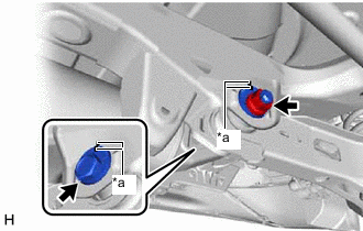
*a Matchmark Align the matchmarks on the No. 2 camber adjust cam, rear suspension toe adjust cam sub-assembly and rear suspension member sub-assembly.
-
Fully tighten the nut.
- Torque:
- 100 N*m { 1020 kgf*cm, 74 ft.*lbf }
Note
-
Hold the rear suspension toe adjust cam sub-assembly while rotating the nut.
-
Make sure that the vehicle is unloaded when fully tightening the nut.
-
-
INSPECT AND ADJUST REAR WHEEL ALIGNMENT
-
PERFORM INITIALIZATION
-
Intelligent clearance sonar system
-
Simple intelligent parking assist system
Parking assist monitor system
-
Automatic headlight beam level control system
-
Adaptive high beam system
-