REAR UPPER ARM REMOVAL
CAUTION / NOTICE / HINT
The necessary procedures (adjustment, calibration, initialization, or registration) that must be performed after parts are removed and installed, or replaced during rear upper control arm assembly removal/installation are shown below.
| Replaced Part or Performed Procedure | Necessary Procedure | Effect/Inoperative Function when Necessary Procedure not Performed | Link |
|---|---|---|---|
| Rear wheel alignment adjustment |
|
|
|
| Suspension, tires, etc. (The vehicle height changes because of suspension or tire replacement) |
|
|
|
| Rear television camera assembly optical axis (Back camera position setting) | Parking assist monitor system | ||
| Initialize No. 1 headlight ECU sub-assembly LH |
|
||
| Rear height control sensor sub-assembly LH | Initialize No. 1 headlight ECU sub-assembly LH |
|
|
| Gas leak from exhaust system is repaired | Inspection After Repair |
|
w/ Canister Pump Module: w/o Canister Pump Module: |
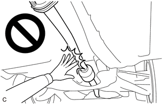
CAUTION:
To prevent burns, do not touch the engine, exhaust pipe or other high temperature components while the engine is hot.
PROCEDURE
-
REMOVE REAR SUSPENSION MEMBER SUB-ASSEMBLY
-
REMOVE REAR UPPER CONTROL ARM ASSEMBLY LH
-
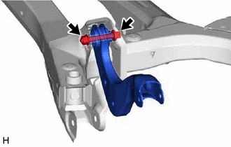
Remove the bolt, nut and rear upper control arm assembly LH from the rear suspension member sub-assembly.
Note
Because the nut has its own stopper, do not turn the nut. Loosen the bolt with the nut secured.
-
-
REMOVE REAR UPPER CONTROL ARM ASSEMBLY RH
Tech Tips
Perform the same procedure as for the LH side.