FRONT SUSPENSION MEMBER INSTALLATION
PROCEDURE
-
INSTALL HOLE PLUG
-
Install the 4 hole plugs to the front suspension crossmember sub-assembly.
Tech Tips
There are 2 different shapes of hole plug.
-
-
INSTALL FRONT SUSPENSION MEMBER PLATE
-
Install the 2 front suspension member plates to the front suspension crossmember sub-assembly.
-
-
INSTALL ENGINE MOVING CONTROL ROD
-
Install the engine moving control rod to the front suspension crossmember sub-assembly with the bolt.
- Torque:
- 200 N*m { 2039 kgf*cm, 148 ft.*lbf }
-
-
TEMPORARILY INSTALL FRONT LOWER NO. 1 SUSPENSION ARM SUB-ASSEMBLY LH
-
Temporarily install the front lower No. 1 suspension arm sub-assembly LH to the front suspension crossmember sub-assembly with the 2 bolts and nut.
-
-
TEMPORARILY INSTALL FRONT LOWER NO. 1 SUSPENSION ARM SUB-ASSEMBLY RH
Tech Tips
Perform the same procedure as for the LH side.
-
INSTALL FRONT STABILIZER BAR
-
INSTALL FRONT NO. 1 STABILIZER BRACKET LH
-
INSTALL FRONT NO. 1 STABILIZER BRACKET RH
Tech Tips
Perform the same procedure as for the LH side.
-
INSTALL STEERING LINK ASSEMBLY
-
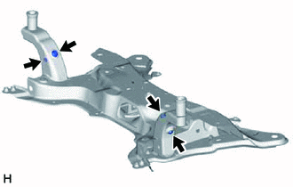
INSTALL FRONT SUSPENSION CROSSMEMBER SUB-ASSEMBLY
-
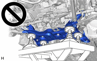
Slowly jack up the front suspension crossmember sub-assembly with an engine lifter using 4 attachments or equivalent tools.
CAUTION:
-
The front suspension crossmember sub-assembly is a very heavy component. Make sure that it is supported securely.
-
If the front suspension crossmember sub-assembly is not securely supported, it may drop, resulting in serious injury.
Note
Use attachments to keep the front suspension crossmember sub-assembly level.
-
-
Install the front suspension crossmember sub-assembly to the vehicle body with the 4 bolts.
- Torque:
- 141 N*m { 1438 kgf*cm, 104 ft.*lbf }
-
Lower the engine lifter.
-
Install the engine moving control rod with the bolt.
- Torque:
- 170 N*m { 1734 kgf*cm, 125 ft.*lbf }
-
Install the 2 wire harness clamp brackets to the front suspension crossmember sub-assembly with the 2 bolts.
- Torque:
- 12 N*m { 122 kgf*cm, 9 ft.*lbf }
-
-
CONNECT FRONT LOWER NO. 1 SUSPENSION ARM SUB-ASSEMBLY LH
-
CONNECT FRONT LOWER NO. 1 SUSPENSION ARM SUB-ASSEMBLY RH
Tech Tips
Perform the same procedure as for the LH side.
-
CONNECT TIE ROD END SUB-ASSEMBLY LH
-
CONNECT TIE ROD END SUB-ASSEMBLY RH
Tech Tips
Perform the same procedure as for the LH side.
-
CONNECT FRONT STABILIZER LINK ASSEMBLY LH
-
Connect the front stabilizer link assembly LH to the front stabilizer bar with the nut.
- Torque:
- 74 N*m { 755 kgf*cm, 55 ft.*lbf }
Note
Do not damage the boot of the ball joint.
Tech Tips
If the ball joint turns together with the nut, use a 6 mm hexagon socket wrench to hold the stud bolt.
-
-
CONNECT FRONT STABILIZER LINK ASSEMBLY RH
Tech Tips
Perform the same procedure as for the LH side.
-
INSTALL REAR SIDE RAIL REINFORCEMENT SUB-ASSEMBLY LH
-
except Rough Road Area Specification Vehicles:
-
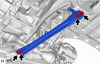
Install the rear side rail reinforcement sub-assembly LH to the front suspension crossmember sub-assembly and vehicle body with the 4 bolts.
- Torque:
- 70 N*m { 714 kgf*cm, 52 ft.*lbf }
-
-
for Rough Road Area Specification Vehicles:
-
Install the rear side rail reinforcement sub-assembly LH to the front suspension crossmember sub-assembly and vehicle body with the 4 bolts.
- Torque:
- 70 N*m { 714 kgf*cm, 52 ft.*lbf }
-
-
-
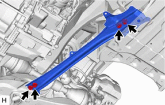
INSTALL REAR SIDE RAIL REINFORCEMENT SUB-ASSEMBLY RH
Tech Tips
Perform the same procedure as for the LH side.
-
CONNECT NO. 1 STEERING COLUMN HOLE COVER SUB-ASSEMBLY
-
CONNECT NO. 2 STEERING INTERMEDIATE SHAFT ASSEMBLY
-
INSTALL COLUMN HOLE COVER SILENCER SHEET
-
INSTALL FRONT WHEELS
-
STABILIZE SUSPENSION
-
FULLY TIGHTEN FRONT LOWER NO. 1 SUSPENSION ARM SUB-ASSEMBLY LH
-
FULLY TIGHTEN FRONT LOWER NO. 1 SUSPENSION ARM SUB-ASSEMBLY RH
-
INSTALL NO. 2 ENGINE UNDER COVER
-
INSTALL REAR ENGINE UNDER COVER LH
-
INSTALL REAR ENGINE UNDER COVER RH
-
INSTALL NO. 1 ENGINE UNDER COVER ASSEMBLY
-
INSPECT AND ADJUST FRONT WHEEL ALIGNMENT
-
PERFORM INITIALIZATION
-
Intelligent clearance sonar system
-
Simple intelligent parking assist system
Parking assist monitor system
-
Automatic headlight beam level control system
-
Adaptive high beam system
-