FRONT LOWER SUSPENSION ARM(for RH Side) INSTALLATION

PROCEDURE
-
TEMPORARILY INSTALL FRONT LOWER NO. 1 SUSPENSION ARM SUB-ASSEMBLY RH
-
Temporarily install the front lower No. 1 suspension arm sub-assembly RH to the front suspension crossmember sub-assembly with the 2 bolts and nut.
-
-
INSTALL FRONT SUSPENSION CROSSMEMBER SUB-ASSEMBLY
-
FULLY TIGHTEN FRONT LOWER NO. 1 SUSPENSION ARM SUB-ASSEMBLY RH
-
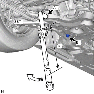
*a Torque Wrench Fulcrum Length 
Turn Using SST, fully tighten the bolt (A).
- SST
- 09961-01270
- Torque:
- Specified tightening torque
- 240 N*m { 2447 kgf*cm, 177 ft.*lbf }
Tech Tips
-
Calculate the torque wrench reading when changing the fulcrum length of the torque wrench.
-
When using SST (fulcrum length of 200 mm (7.87 in.)) + torque wrench (fulcrum length of 600 mm (1.97 ft.)):
180 N*m (1835 kgf*cm, 133 ft.*lbf)
-
Fully tighten the bolt (B).
- Torque:
- 125 N*m { 1275 kgf*cm, 92 ft.*lbf }
Note
Because the nut has its own stopper, do not turn the nut. Tighten the bolt with the nut secured.
-
-
INSTALL NO. 2 ENGINE UNDER COVER
-
INSTALL REAR ENGINE UNDER COVER LH
-
INSTALL REAR ENGINE UNDER COVER RH
-
INSTALL NO. 1 ENGINE UNDER COVER ASSEMBLY
-
INSPECT AND ADJUST FRONT WHEEL ALIGNMENT
-
PERFORM INITIALIZATION
-
Intelligent clearance sonar system
-
Simple intelligent parking assist system
Parking assist monitor system
-
Automatic headlight beam level control system
-
Adaptive high beam system
-