REAR AXLE CARRIER INSTALLATION
CAUTION / NOTICE / HINT
Note
-
When removing or installing the rear disc brake caliper assembly, pushing back the disc brake piston may cause a large clearance between the brake pads and brake disc. When the brake pedal is depressed with a large clearance between the brake pads and the brake disc, DTC C1214 related to abnormal brake fluid pressure may be stored. Make sure to clear any DTCs after performing this step.
-
While the auxiliary battery is connected, even if the power switch is off, the brake control system activates when the brake pedal is depressed or any door courtesy switch turns on. Therefore, when servicing the brake system components, do not operate the brake pedal or open/close the doors while the auxiliary battery is connected.
Tech Tips
-
Use the same procedure for the RH side and LH side.
-
The following procedure is for the LH side.
PROCEDURE
-
TEMPORARILY INSTALL REAR AXLE CARRIER SUB-ASSEMBLY
-
Temporarily install the rear axle carrier sub-assembly to the rear upper control arm assembly with the bolt and nut.
Note
-
Insert the bolt with the threaded end facing the rear of the vehicle.
-
Because the nut has its own stopper, do not turn the nut. Tighten the bolt with the nut secured.
-
-
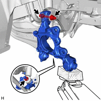
Temporarily install the rear shock absorber assembly to the rear axle carrier sub-assembly with the nut and plate washer.
Note
Hold the rear axle carrier pin while rotating the nut.
-
Install the rear trailing arm assembly to the rear axle carrier sub-assembly with the 2 bolts.
- Torque:
- 135 N*m { 1377 kgf*cm, 100 ft.*lbf }
-
-
INSTALL FLEXIBLE HOSE BRACKET
-
Install the flexible hose bracket to the rear axle carrier sub-assembly with the bolt.
- Torque:
- 29 N*m { 296 kgf*cm, 21 ft.*lbf }
-
-
TEMPORARILY INSTALL REAR NO. 1 SUSPENSION ARM ASSEMBLY
-
INSTALL REAR LOWER COIL SPRING INSULATOR
-
INSTALL REAR COIL SPRING
-
STABILIZE SUSPENSION
-
INSTALL REAR UPPER CONTROL ARM ASSEMBLY
-
Install the rear upper control arm assembly to the rear axle carrier sub-assembly with the bolt.
- Torque:
- 73 N*m { 744 kgf*cm, 54 ft.*lbf }
Note
Because the nut has its own stopper, do not turn the nut. Tighten the bolt with the nut secured.
-
-
INSTALL REAR NO. 1 SUSPENSION ARM ASSEMBLY
-
INSTALL REAR NO. 2 SUSPENSION ARM ASSEMBLY
-
Install the rear No. 2 suspension arm assembly (rear axle carrier sub-assembly side) with the bolt.
-
-
INSTALL REAR SHOCK ABSORBER ASSEMBLY
-
INSTALL REAR STABILIZER LINK ASSEMBLY
-
INSTALL REAR AXLE HUB AND BEARING ASSEMBLY
-
CONNECT SKID CONTROL SENSOR WIRE
-
INSTALL REAR DISC
-
INSTALL REAR DISC BRAKE CALIPER ASSEMBLY
-
CONNECT NO. 3 PARKING BRAKE CABLE ASSEMBLY
-
INSTALL PARKING BRAKE LEVER PROTECTOR
-
ADJUST PARKING BRAKE
-
INSTALL REAR HEIGHT CONTROL SENSOR SUB-ASSEMBLY LH (for LH Side)
-
INSTALL REAR FLOOR SIDE MEMBER COVER LH (for LH Side)
w/ Canister Pump Module: Click here
w/o Canister Pump Module: Click here
-
INSTALL NO. 1 FLOOR UNDER COVER ASSEMBLY (for RH Side)
w/ Canister Pump Module: Click here
w/o Canister Pump Module: Click here
-
INSTALL REAR WHEEL
-
INSTALL REAR NO. 2 SUSPENSION ARM ASSEMBLY
-
Install the rear No. 2 suspension arm assembly (rear suspension member sub-assembly side) with the nut.
-
-
CONNECT CABLE TO NEGATIVE AUXILIARY BATTERY TERMINAL
-
Connect the reservoir level switch connector.
-
Connect the cable to the negative (-) auxiliary battery terminal.
-
Turn the power switch on (READY).
-
Depress the brake pedal and release it.
-
Clear the DTCs.
-
-
INSPECT AND ADJUST REAR WHEEL ALIGNMENT
-
CHECK FOR SPEED SENSOR SIGNAL
-
PERFORM INITIALIZATION
-
Intelligent clearance sonar system
-
Simple intelligent parking assist system
Parking assist monitor system
-
Automatic headlight beam level control system
-
Adaptive high beam system
-