REAR AXLE CARRIER REMOVAL
CAUTION / NOTICE / HINT
The necessary procedures (adjustment, calibration, initialization, or registration) that must be performed after parts are removed and installed, or replaced during rear axle carrier sub-assembly removal/installation are shown below.
| Replaced Part or Performed Procedure | Necessary Procedure | Effect/Inoperative Function when Necessary Procedure not Performed | Link |
|---|---|---|---|
| Auxiliary battery terminal is disconnected/reconnected | Memorize steering angle neutral point | Lane departure alert system (w/ Steering control) | |
| Intelligent clearance sonar system*1 | |||
| Simple intelligent parking assist system*1 | |||
| Pre-crash safety system | |||
| Adaptive high beam system | |||
| Parking assist monitor system | |||
| Initialize back door lock | Power door lock control system | ||
| Rear wheel alignment adjustment |
|
|
|
| Suspension, tires, etc. (The vehicle height changes because of suspension or tire replacement) |
|
|
|
| Rear television camera assembly optical axis (Back camera position setting) | Parking assist monitor system | ||
| Initialize No. 1 headlight ECU sub-assembly LH |
|
||
| Rear height control sensor sub-assembly LH*2 | Initialize No. 1 headlight ECU sub-assembly LH |
|
Click here Click here
*2: for LH Side
*3: w/ Adaptive High Beam System
Note
-
When removing or installing the rear disc brake caliper assembly, pushing back the disc brake piston may cause a large clearance between the brake pads and brake disc. When the brake pedal is depressed with a large clearance between the brake pads and the brake disc, DTC C1214 related to abnormal brake fluid pressure may be stored. Make sure to clear any DTCs after performing this step.
-
While the auxiliary battery is connected, even if the power switch is off, the brake control system activates when the brake pedal is depressed or any door courtesy switch turns on. Therefore, when servicing the brake system components, do not operate the brake pedal or open/close the doors while the auxiliary battery is connected.
Tech Tips
-
Use the same procedure for the RH side and LH side.
-
The following procedure is for the LH side.
PROCEDURE
-
PRECAUTION
Note
After turning the power switch off, waiting time may be required before disconnecting the cable from the negative (-) auxiliary battery terminal. Therefore, make sure to read the disconnecting the cable from the negative (-) auxiliary battery terminal notices before proceeding with work.
-
DISABLE BRAKE CONTROL
-
REMOVE REAR WHEEL
-
REMOVE REAR FLOOR SIDE MEMBER COVER LH (for LH Side)
w/ Canister Pump Module: Click here
w/o Canister Pump Module: Click here
-
REMOVE NO. 1 FLOOR UNDER COVER ASSEMBLY (for RH Side)
w/ Canister Pump Module: Click here
w/o Canister Pump Module: Click here
-
LOOSEN NO. 1 WIRE ADJUSTING NUT
for LHD: Click here
for RHD: Click here
-
REMOVE PARKING BRAKE LEVER PROTECTOR
-
SEPARATE NO. 3 PARKING BRAKE CABLE ASSEMBLY
-
SEPARATE REAR DISC BRAKE CALIPER ASSEMBLY
-
REMOVE REAR DISC
-
DISCONNECT SKID CONTROL SENSOR WIRE
-
REMOVE REAR AXLE HUB AND BEARING ASSEMBLY
-
REMOVE FLEXIBLE HOSE BRACKET
-
Remove the bolt and flexible hose bracket from the rear axle carrier sub-assembly.
-
-
REMOVE REAR HEIGHT CONTROL SENSOR SUB-ASSEMBLY LH (for LH Side)
-
REMOVE REAR STABILIZER LINK ASSEMBLY
-
REMOVE REAR COIL SPRING
-
REMOVE REAR LOWER COIL SPRING INSULATOR
-
REMOVE REAR NO. 1 SUSPENSION ARM ASSEMBLY
-
REMOVE REAR AXLE CARRIER SUB-ASSEMBLY
-
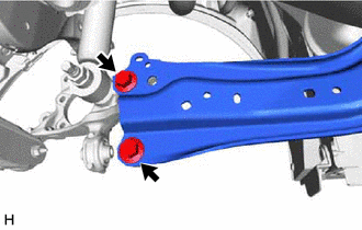
Loosen the 2 bolts of the rear trailing arm assembly.
-
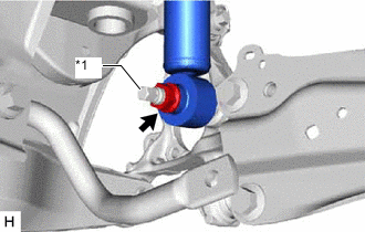
*1 Rear Axle Carrier Pin Loosen the nut of the rear shock absorber assembly.
Note
Hold the rear axle carrier pin while rotating the nut.
-
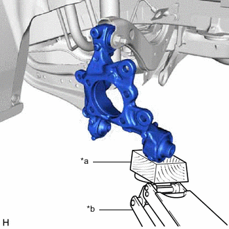
*a Wooden Block *b Jack Using a jack and a wooden block, support the rear axle carrier sub-assembly.
Note
-
When jacking up the rear axle carrier sub-assembly, be sure to jack it up slowly.
-
Make sure to perform this operation with the vehicle kept as low as possible.
-
-
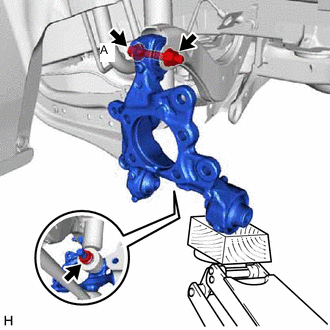
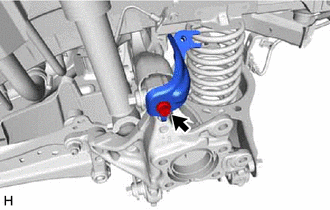
Loosen the bolt (A).
Note
Because the nut has its own stopper, do not turn the nut. Loosen the bolt with the nut secured.
-
Remove the 2 bolts and separate the rear trailing arm assembly from the rear axle carrier sub-assembly.
-
Remove the nut and plate washer, and separate the rear shock absorber assembly from the rear axle carrier sub-assembly.
Note
Hold the rear axle carrier pin while rotating the nut.
-
Remove the bolt (A), nut and rear axle carrier sub-assembly from the rear upper control arm assembly.
Note
Because the nut has its own stopper, do not turn the nut. Loosen the bolt with the nut secured.
-