REAR TRAILING ARM INSTALLATION
CAUTION / NOTICE / HINT
Tech Tips
-
Use the same procedure for the RH side and LH side.
-
The following procedure is for the LH side.
PROCEDURE
-
INSTALL REAR SUSPENSION ARM BRACKET
-
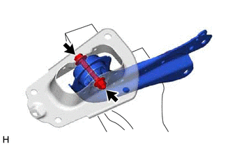
Temporarily install the rear suspension arm bracket to the rear trailing arm assembly with the bolt and nut.
Note
-
Because the bolt has its own stopper, do not turn the bolt. Tighten the nut with the bolt secured.
-
Insert the bolt from the inside of the vehicle.
-
-
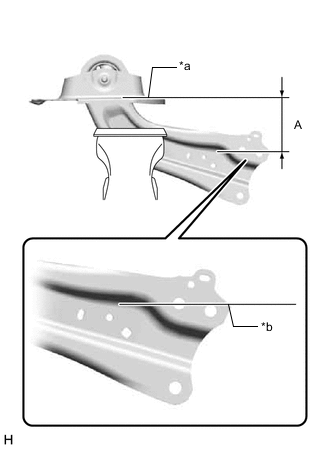
*a Upper Surface of Rear Suspension Arm Bracket *b Edge of Rear Trailing Arm Assembly Position the rear trailing arm assembly as shown in the illustration.
Reference Length (A) 116 mm (4.57 in.) -
Fully tighten the nut.
- Torque:
- 120 N*m { 1224 kgf*cm, 89 ft.*lbf }
Note
Because the bolt has its own stopper, do not turn the bolt. Tighten the nut with the bolt secured.
-
-
INSTALL REAR SUSPENSION ARM COVER
-
Engage the 4 claws and install the rear suspension arm cover.
-
-
INSTALL REAR TRAILING ARM ASSEMBLY
-
Using a transmission jack and a wooden block, support the rear No. 2 suspension arm assembly.
Note
-
When jacking up the rear No. 2 suspension arm assembly, be sure to jack it up slowly.
-
Make sure to perform this operation with the vehicle kept as low as possible.
-
-
Install the rear trailing arm assembly to the vehicle with the 4 bolts.
- Torque:
- 90 N*m { 918 kgf*cm, 66 ft.*lbf }
-
Install the rear trailing arm assembly to the rear axle carrier sub-assembly with the 2 bolts.
- Torque:
- 135 N*m { 1377 kgf*cm, 100 ft.*lbf }
-
-
INSTALL SKID CONTROL SENSOR WIRE
-
Install the skid control sensor wire to the rear trailing arm assembly with the bolt.
- Torque:
- 19 N*m { 194 kgf*cm, 14 ft.*lbf }
-
Engage the 2 clamps.
-
-
INSTALL NO. 3 PARKING BRAKE CABLE ASSEMBLY
-
Install the No. 3 parking brake cable assembly to the rear trailing arm assembly with the nut.
- Torque:
- 15.5 N*m { 158 kgf*cm, 11 ft.*lbf }
-
-
INSTALL REAR STABILIZER LINK ASSEMBLY
-
INSTALL REAR FLOOR SIDE MEMBER COVER LH (for LH Side)
w/ Canister Pump Module: Click here
w/o Canister Pump Module: Click here
-
INSTALL NO. 1 FLOOR UNDER COVER ASSEMBLY (for RH Side)
w/ Canister Pump Module: Click here
w/o Canister Pump Module: Click here
-
INSTALL REAR WHEEL
-
INSPECT AND ADJUST REAR WHEEL ALIGNMENT
-
PERFORM INITIALIZATION
-
Intelligent clearance sonar system
-
Simple intelligent parking assist system
Parking assist monitor system
-
Automatic headlight beam level control system
-
Adaptive high beam system
-