OIL COOLER INSTALLATION
PROCEDURE
-
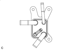
INSTALL NO. 1 MOTOR COOLING HOSE
Tech Tips
Perform this procedure only when replacement of the motor cooling cooler is necessary.
-

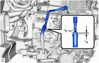
ATF Application Area Coat the pipe of the motor cooling cooler with a small amount of ATF as shown in the illustration.
-
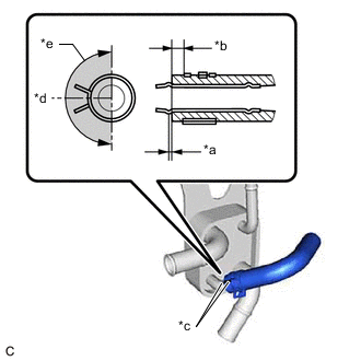
*a 0 to 3 mm (0 to 0.118 in.) *b 2 to 7 mm (0.0787 to 0.276 in.) *c Paint Mark *d Center of Paint Mark *e 180° Claw of Clip Location Install the No. 1 motor cooling hose to the motor cooling cooler and slide the clip to secure it.
Note
-
Be careful not to deform the motor cooling cooler.
-
Make sure to align the paint mark on the No. 1 motor cooling hose with the paint mark on the motor cooling cooler.
-
Make sure that the claws of the clip are positioned within the area shown in the illustration.
-
-
-
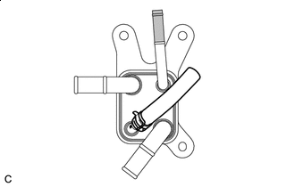
INSTALL NO. 2 MOTOR COOLING HOSE
Tech Tips
Perform this procedure only when replacement of the motor cooling cooler is necessary.
-
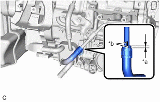
ATF Application Area Coat the pipe of the motor cooling cooler with a small amount of ATF as shown in the illustration.
-
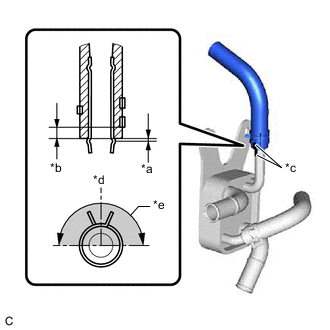
*a 0 to 3 mm (0 to 0.118 in.) *b 2 to 7 mm (0.0787 to 0.276 in.) *c Paint Mark *d Center of Paint Mark *e 180° Claw of Clip Location Install the No. 2 motor cooling hose to the motor cooling cooler and slide the clip to secure it.
Note
-
Be careful not to deform the motor cooling cooler.
-
Make sure to align the paint mark on the No. 2 motor cooling hose with the paint mark on the motor cooling cooler.
-
Make sure that the claws of the clip are positioned within the area shown in the illustration.
-
-
-
INSTALL MOTOR COOLING COOLER
-
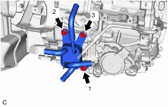
Temporarily install the motor cooling cooler to the hybrid vehicle transaxle assembly with the 3 bolts.
-
Tighten the 3 bolts in the order shown in the illustration.
- Torque:
- 11.5 N*m { 117 kgf*cm, 8 ft.*lbf }
-
*a 2 to 7 mm (0.0787 to 0.276 in.) *b Paint Mark Install the No. 2 motor cooling pipe to the No. 2 motor cooling hose and slide the clip to secure it.
Note
Make sure to align the paint mark on the No. 2 motor cooling pipe with the paint mark on the No. 2 motor cooling hose.
-
Temporarily install the No. 2 motor cooling pipe to the hybrid vehicle transaxle assembly with the union bolt and a new gasket.
-
Install the No. 1 oil cooler tube clamp to the hose bracket with the bolt.
- Torque:
- 11.5 N*m { 117 kgf*cm, 8 ft.*lbf }
-
Tighten the union bolt to install the No. 2 motor cooling pipe.
- Torque:
- 35 N*m { 357 kgf*cm, 26 ft.*lbf }
-
*a 2 to 7 mm (0.0787 to 0.276 in.) *b Paint Mark Connect the No. 1 motor cooling hose to the No. 1 motor cooling pipe and slide the clip to secure it.
Note
Make sure to align the paint mark on the No. 1 motor cooling pipe with the paint mark on the No. 1 motor cooling hose.
-
-
CONNECT OUTLET NO. 1 HYBRID WATER PUMP HOSE
-
CONNECT INLET HYBRID RADIATOR HOSE
-
INSTALL AIR CLEANER CASE SUB-ASSEMBLY
-
INSTALL AIR CLEANER FILTER ELEMENT SUB-ASSEMBLY
-
INSTALL AIR CLEANER CAP SUB-ASSEMBLY
-
INSTALL INVERTER WITH CONVERTER ASSEMBLY
-
INSPECT HYBRID TRANSAXLE FLUID
-
INSPECT FOR HYBRID TRANSAXLE FLUID LEAK
-
INSTALL REAR ENGINE UNDER COVER LH
-
INSTALL NO. 1 ENGINE UNDER COVER ASSEMBLY