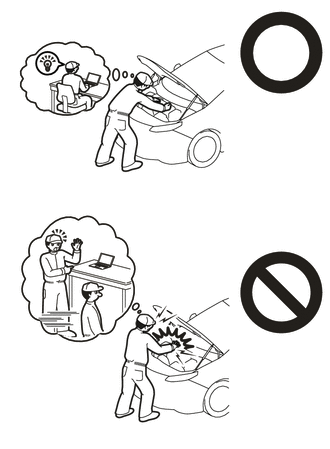
OIL COOLER REMOVAL
CAUTION / NOTICE / HINT
The necessary procedures (adjustment, calibration, initialization, or registration) that must be performed after parts are removed and installed, or replaced during motor cooling cooler removal/installation are shown below.
| Replaced Part or Performed Procedure | Necessary Procedure | Effect/Inoperative Function when Necessary Procedure not Performed | Link |
|---|---|---|---|
| Auxiliary battery terminal is disconnected/reconnected | Memorize steering angle neutral point | Lane departure alert system (w/ Steering Control) | |
| Intelligent clearance sonar system*1 | |||
| Simple intelligent parking assist system*1 | |||
| Pre-crash safety system | |||
| Adaptive high beam system | |||
| Parking assist monitor system | |||
| Initialize back door lock | Power door lock control system | ||
| Replacement of inverter with converter assembly | Resolver learning |
|
|
for SFI system (w/ Canister Pump Module) |
Perform Vehicle Identification Number (VIN) registration | MIL comes on | |
for SFI system (w/o Canister Pump Module) |
Perform Vehicle Identification Number (VIN) or frame number registration | MIL comes on |
Click here Click here
CAUTION:
-
Orange wire harnesses and connectors indicate high-voltage circuits. To prevent electric shock, always follow the procedure described in the repair manual.
-

To prevent electric shock, wear insulated gloves when working on wire harnesses and components of the high voltage system.
PROCEDURE
-
REMOVE NO. 1 ENGINE UNDER COVER ASSEMBLY
-
REMOVE REAR ENGINE UNDER COVER LH
-
REMOVE INVERTER WITH CONVERTER ASSEMBLY
-
REMOVE AIR CLEANER CAP SUB-ASSEMBLY
-
REMOVE AIR CLEANER FILTER ELEMENT SUB-ASSEMBLY
-
REMOVE AIR CLEANER CASE SUB-ASSEMBLY
-
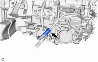
DISCONNECT INLET HYBRID RADIATOR HOSE
-
DISCONNECT OUTLET NO. 1 HYBRID WATER PUMP HOSE
-
REMOVE MOTOR COOLING COOLER
-
Slide the clip and disconnect the No. 1 motor cooling hose from the No. 1 motor cooling pipe.
-
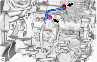
Remove the bolt and No. 1 oil cooler tube clamp from the hose bracket.
-
Remove the union bolt and gasket to disconnect the No. 2 motor cooling pipe from the hybrid vehicle transaxle assembly.
-
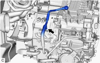
Slide the clip and remove the No. 2 motor cooling pipe from the No. 2 motor cooling hose.
-
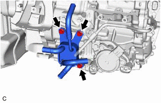
Remove the 3 bolts and motor cooling cooler from the hybrid vehicle transaxle assembly.
Note
Make sure not to remove the No. 1 motor cooling hose and No. 2 motor cooling hose from the motor cooling cooler as the motor cooling cooler may be deformed.
-