HYBRID VEHICLE TRANSAXLE REMOVAL
CAUTION / NOTICE / HINT
The necessary procedures (adjustment, calibration, initialization, or registration) that must be performed after parts are removed and installed, or replaced during hybrid vehicle transaxle assembly removal/installation are shown below.
| Replaced Part or Performed Procedure | Necessary Procedure | Effect/Inoperative Function when Necessary Procedure not Performed | Link |
|---|---|---|---|
| Auxiliary battery terminal is disconnected/reconnected | Memorize steering angle neutral point | Lane departure alert system (w/ Steering Control) | |
| Intelligent clearance sonar system*1 | |||
| Simple intelligent parking assist system*1 | |||
| Pre-crash safety system | |||
| Adaptive high beam system | |||
| Parking assist monitor system | |||
| Initialize back door lock | Power door lock control system | ||
for SFI system (w/ Canister Pump Module) |
Inspection after repair |
|
|
for SFI system (w/o Canister Pump Module) |
Inspection after repair |
|
|
| Suspension, tires, etc. (The vehicle height changes because of suspension or tire replacement) |
|
|
|
| Rear television camera assembly optical axis (Back camera position setting) | Parking assist monitor system | ||
| Initialize No. 1 headlight ECU sub-assembly LH |
|
||
| Front wheel alignment adjustment |
|
|
|
| Replacement of hybrid vehicle transaxle assembly |
|
|
|
| Replacement of inverter with converter assembly | Resolver learning | ||
for SFI system (w/ Canister Pump Module) |
Perform Vehicle Identification Number (VIN) registration | MIL comes on | |
for SFI system (w/o Canister Pump Module) |
Perform Vehicle Identification Number (VIN) or frame number registration | MIL comes on |
Click here Click here
CAUTION:
-
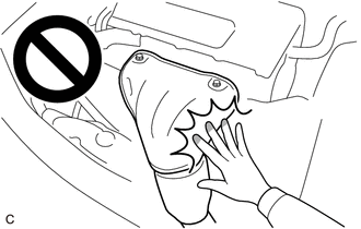
Orange wire harnesses and connectors indicate high-voltage circuits. To prevent electric shock, always follow the procedure described in the repair manual.
-

To prevent electric shock, wear insulated gloves when working on wire harnesses and components of the high voltage system.
-
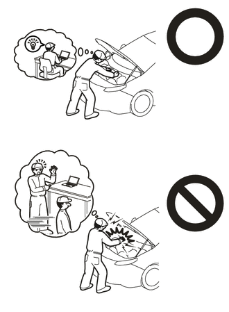
To prevent burns, do not touch the engine, exhaust manifold or other high temperature components while the engine is hot.
-
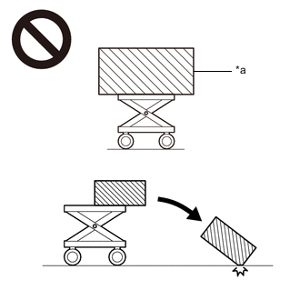
*a An Object Exceeding Weight Limit of Engine Lifter The engine assembly with hybrid vehicle transaxle assembly is very heavy. Be sure to follow the procedure described in the repair manual, or the engine lifter may suddenly drop or the engine assembly with transaxle may fall off the engine lifter.
PROCEDURE
-
PERFORM RESOLVER INITIALIZATION
Note
If it is necessary to replace the hybrid vehicle transaxle assembly, make sure to perform resolver initialization before starting work.
-
REMOVE ENGINE ASSEMBLY WITH TRANSAXLE
-
INSTALL ENGINE HANGERS
-
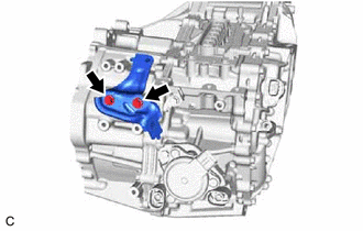
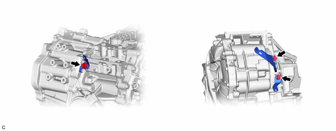
DISCONNECT ENGINE WIRE
-
Disconnect the motor revolution sensor wire connector.
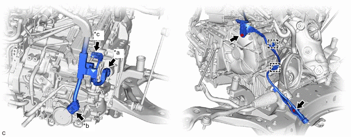
*a Motor Revolution Sensor Wire Connector *b Shift Control Actuator Assembly Connector *c Motor Temperature Sensor Connector - - -
Disconnect the shift control actuator assembly connector.
-
Disconnect the motor temperature sensor connector.
-
Remove the 2 bolts.
-
Disengage the 2 clamps to disconnect the engine wire from the hybrid vehicle transaxle assembly.
-
-
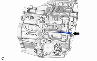
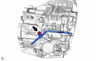
DISCONNECT AIR CONDITIONING WIRE
-
Remove the bolt.
-
Disengage the guide to disconnect the air conditioning wire from the hybrid vehicle transaxle assembly.
-
-
REMOVE STARTER HOLE INSULATOR
-
Remove the 2 bolts and starter hole insulator from the engine assembly.
-
-
REMOVE ENGINE ASSEMBLY
-
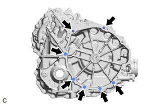
Remove the 7 bolts and engine assembly from the hybrid vehicle transaxle assembly.
Note
-
To avoid damaging the knock pins, do not pry between the hybrid vehicle transaxle assembly and engine assembly.
-
To prevent the splines of the transmission input damper assembly from becoming misaligned, do not allow the hybrid vehicle transaxle assembly to hit the transmission input damper assembly during hybrid vehicle transaxle assembly removal and installation.
-
-
-
REMOVE FRONT SUSPENSION CROSSMEMBER SUB-ASSEMBLY
-
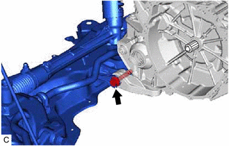
Remove the bolt and front suspension crossmember sub-assembly from the No. 2 engine moving control rod.
-
-
REMOVE NO. 2 ENGINE MOVING CONTROL ROD
-
Remove the 4 bolts and No. 2 engine moving control rod from the hybrid vehicle transaxle assembly.
-
-
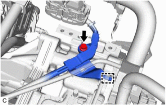
REMOVE MOTOR CABLE
-
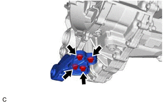
REMOVE MOTOR COOLING COOLER
-
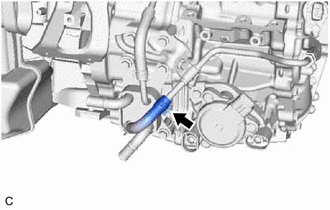
Slide the clip and disconnect the No. 1 motor cooling hose from the No. 1 motor cooling pipe.
-
Remove the bolt and No. 1 oil cooler tube clamp from the hose bracket.
-
Remove the union bolt and gasket to disconnect the No. 2 motor cooling pipe from the hybrid vehicle transaxle assembly.
-
Remove the 3 bolts and motor cooling cooler with No. 2 motor cooling pipe from the hybrid vehicle transaxle assembly.
Note
Make sure not to remove the No. 1 motor cooling hose and No. 2 motor cooling hose from the motor cooling cooler as the motor cooling cooler may be deformed.
-
-
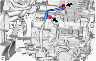
REMOVE NO. 1 MOTOR COOLING PIPE
-
Loosen the flare nut of the No. 1 motor cooling pipe and disconnect the No. 1 motor cooling pipe from the union.
-
Remove the bolt, No. 1 oil cooler tube clamp and No. 1 motor cooling pipe from the hose bracket.
-
-
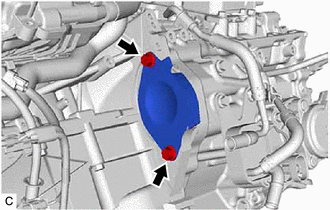
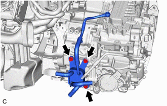
REMOVE HOSE BRACKET
-
Remove the 2 bolts and hose bracket from the hybrid vehicle transaxle assembly.
-
-
REMOVE WIRE HARNESS CLAMP BRACKET
-
Remove the 3 bolts and 3 wire harness clamp brackets from the hybrid vehicle transaxle assembly.
-
-
REMOVE TRANSAXLE HOUSING PLUG
-
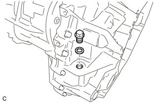
Remove the transaxle housing plug and gasket from the hybrid vehicle transaxle assembly.
-
-
REMOVE STUD BOLT
-
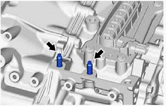
Using a E8 "TORX" socket wrench, remove the 2 stud bolts from the hybrid vehicle transaxle assembly.
-