ELECTRONIC SHIFT LEVER SYSTEM "P" Position Switch Indicator Light Circuit
DESCRIPTION
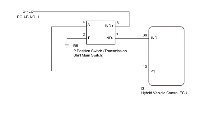
The P position switch (transmission shift main switch) indicator light comes on when the P position switch (transmission shift main switch) is pressed (park (P) is selected) and turns off when a shift state other than park (P) is selected or a system malfunction occurs. A warning message will also be displayed on the multi-information display if a malfunction occurs.
WIRING DIAGRAM
PROCEDURE
-
CHECK P POSITION SWITCH (TRANSMISSION SHIFT MAIN SWITCH) (INDICATOR LIGHT)
-
Turn the power switch on (IG).
-
Depress the brake pedal and select neutral (N).
-
Operate the P position switch (transmission shift main switch) and check the condition of the indicator light.
Result Condition of Indicator Light Proceed to Indicator light illuminates A Indicator light does not come on. B -
Turn the power switch off.
B 
CHECK HARNESS AND CONNECTOR (P POSITION SWITCH (TRANSMISSION SHIFT MAIN SWITCH) POWER SOURCE CIRCUIT) Click here
A 
-
-
CHECK P POSITION SWITCH (TRANSMISSION SHIFT MAIN SWITCH) (INDICATOR LIGHT)
-
Disconnect the I3 hybrid vehicle control ECU connector.
-
Turn the power switch on (IG).
-
Inspect the P position switch (transmission shift main switch) indicator light condition.
Result Result Proceed to Indicator light does not go off. (Remains on) A Indicator light goes off. B Note
Turning the power switch on (IG) with the hybrid vehicle control ECU connector disconnected causes other DTCs to be stored. Clear the DTCs after performing this inspection.
-
Turn the power switch off.
-
Reconnect the I3 hybrid vehicle control ECU connector.
B 
REPLACE HYBRID VEHICLE CONTROL ECU Click here
A
-
-
CHECK HARNESS AND CONNECTOR (HYBRID VEHICLE CONTROL ECU - P POSITION SWITCH (TRANSMISSION SHIFT MAIN SWITCH))
-
Disconnect the I3 hybrid vehicle control ECU connector.
-
Disconnect the I56 P position switch (transmission shift main switch) connector.
-
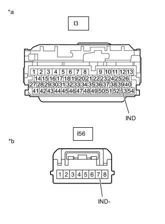
*a Front view of wire harness connector
(to Hybrid Vehicle Control ECU)
*b Front view of wire harness connector
(to P Position Switch (Transmission Shift Main Switch))
Measure the resistance according to the value(s) in the table below.
Standard Resistance (Check for Short) Tester Connection Condition Specified Condition I3-39 (IND) or I56-7 (IND-) - Body ground and other terminals Power switch off 10 kΩ or higher -
Reconnect the I56 P position switch (transmission shift main switch) connector.
-
Reconnect the I3 hybrid vehicle control ECU connector.
Result Proceed to OK NG
OK
REPLACE P POSITION SWITCH (TRANSMISSION SHIFT MAIN SWITCH)
NG
REPAIR OR REPLACE HARNESS OR CONNECTOR
-
-
CHECK HARNESS AND CONNECTOR (P POSITION SWITCH (TRANSMISSION SHIFT MAIN SWITCH) POWER SOURCE CIRCUIT)
-
Disconnect the I56 P position switch (transmission shift main switch) connector.
-
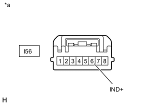
*a Front view of wire harness connector
(to P Position Switch (Transmission Shift Main Switch))
Measure the voltage according to the value(s) in the table below.
Standard Voltage Tester Connection Condition Specified Condition I56-6 (IND+) - Body ground Power switch off 9 to 14 V -
Reconnect the I56 P position switch (transmission shift main switch) connector.
Result Proceed to OK NG
NG
CHECK AND REPAIR POWER SOURCE CIRCUIT
OK
-
-
INSPECT P POSITION SWITCH (TRANSMISSION SHIFT MAIN SWITCH)
-
Disconnect the I56 P position switch (transmission shift main switch) connector.
-
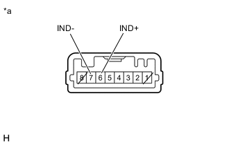
*a Component without harness connected
(P Position Switch (Transmission Shift Main Switch))
Apply auxiliary battery voltage between terminals I56-6 (IND+) and I56-7 (IND-) and check the indicator light.
Result Condition Specified Condition Auxiliary battery voltage applied between terminals I56-6 (IND+) and I56-7 (IND-) Comes on Tech Tips
Terminals 1 and 8 of the P position switch (transmission shift main switch) side connector are empty.
-
Reconnect the I56 P position switch (transmission shift main switch) connector.
Result Proceed to OK NG
NG
REPLACE P POSITION SWITCH (TRANSMISSION SHIFT MAIN SWITCH)
OK
-
-
CHECK HARNESS AND CONNECTOR (HYBRID VEHICLE CONTROL ECU - P POSITION SWITCH (TRANSMISSION SHIFT MAIN SWITCH))
-
Disconnect the I3 hybrid vehicle control ECU connector.
-
Disconnect the I56 P position switch (transmission shift main switch) connector.
-
*a Front view of wire harness connector
(to Hybrid Vehicle Control ECU)
*b Front view of wire harness connector
(to P Position Switch (Transmission Shift Main Switch))
Measure the resistance according to the value(s) in the table below.
Standard Resistance (Check for Open) Tester Connection Condition Specified Condition I3-39 (IND) - I56-7 (IND-) Power switch off Below 1 Ω -
Reconnect the I56 P position switch (transmission shift main switch) connector.
-
Reconnect the I3 hybrid vehicle control ECU connector.
Result Proceed to OK NG
OK
REPLACE HYBRID VEHICLE CONTROL ECU Click here
NG
REPAIR OR REPLACE HARNESS OR CONNECTOR
-