LANE DEPARTURE ALERT SYSTEM(w/ Steering Control) Steering Pad Switch Circuit
DESCRIPTION
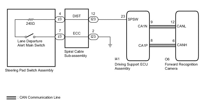
The driving support ECU assembly receives a lane departure alert switch signal from the steering pad switch assembly and sends the signal to the forward recognition camera via CAN communication.
WIRING DIAGRAM
CAUTION / NOTICE / HINT
Note
The vehicle is equipped with a Supplemental Restraint System (SRS) which includes components such as airbags. Before servicing (including removal or installation of parts), be sure to read the precaution for Supplemental Restraint System.
PROCEDURE
-
READ VALUE USING GTS (CAN BUS CHECK)
-
Connect the GTS to the DLC3.
-
Turn the power switch on (IG).
-
Turn the GTS on.
-
Enter the following menus: System Select / Can Bus Check.
CAN Bus CheckResult Result Proceed to All of the ECUs and sensors that are currently connected to the CAN communication system are displayed A None of the ECUs and sensors that are currently connected to the CAN communication system are displayed, or some of them are not displayed B
B 
GO TO CAN COMMUNICATION SYSTEM Click here
A 
-
-
CHECK FOR DTCs (HEALTH CHECK)
-
Connect the GTS to the DLC3.
-
Turn the power switch on (IG).
-
Turn the GTS on.
-
Enter the following menus: System Select / Health Check.
-
Check DTCs.
-
Turn the power switch off.
Result Result Proceed to No DTCs are output. A DTCs are output. B
B
GO TO DTC CHART
A
-
-
INSPECT STEERING PAD SWITCH ASSEMBLY
-
Remove the horn button assembly.
-
Disconnect the z3 steering pad switch assembly connector.
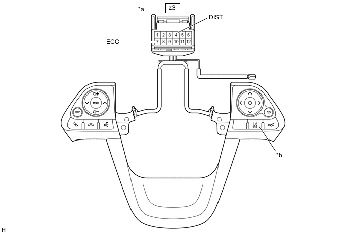
*a Front view of wire harness connector
(Steering Pad Switch Assembly)
*b Lane Departure Alert Main Switch -
Measure the resistance according to the value(s) in the table below.
Standard Resistance Tester Connection Condition Specified Condition z3-4 (DIST) - z3-7 (ECC) Lane departure alert main switch pushed and held 228 to 252 Ω Lane departure alert main switch not pushed 10 kΩ or higher -
Reconnect the z3 steering pad switch assembly connector.
-
Reinstall the horn button assembly.
Result Proceed to OK NG
NG
REPLACE STEERING PAD SWITCH ASSEMBLY Click here
OK
-
-
INSPECT SPIRAL CABLE SUB-ASSEMBLY
-
Remove the spiral cable sub-assembly.
-
Inspect the spiral cable sub-assembly.
Result Proceed to OK NG
NG
REPLACE SPIRAL CABLE SUB-ASSEMBLY Click here
OK
-
-
CHECK HARNESS AND CONNECTOR (SPIRAL CABLE SUB-ASSEMBLY - DRIVING SUPPORT ECU ASSEMBLY)
-
Disconnect the I23 spiral cable sub-assembly connector.
-
Disconnect the I41 driving support ECU assembly connector.
-
Measure the resistance according to the value(s) in the table below.
Standard Resistance (Check for Open) Tester Connection Condition Specified Condition I23-12 (DIST) - I41-23 (SPSW) Always Below 1 Ω Standard Resistance (Check for Short) Tester Connection Condition Specified Condition I23-12 (DIST) or I41-23 (SPSW) - Body ground Always 10 kΩ or higher -
Connect the I41 driving support ECU assembly connector.
-
Connect the I23 spiral cable sub-assembly connector.
Result Proceed to OK NG
NG
REPAIR OR REPLACE HARNESS OR CONNECTOR
OK
-
-
CHECK HARNESS AND CONNECTOR (SPIRAL CABLE SUB-ASSEMBLY - BODY GROUND)
-
Disconnect the I23 spiral cable sub-assembly connector.
-
Measure the resistance according to the value(s) in the table below.
Standard Resistance (Check for Open) Tester Connection Condition Specified Condition I23-2 (ECC) - Body ground Always Below 1 Ω -
Reconnect the I23 spiral cable sub-assembly connector.
Result Proceed to OK NG
OK
PROCEED TO NEXT SUSPECTED AREA SHOWN IN PROBLEM SYMPTOMS TABLE Click here
NG
REPAIR OR REPLACE HARNESS OR CONNECTOR
-