FORWARD RECOGNITION CAMERA SYSTEM, Diagnostic DTC:U0182
| DTC Code | DTC Name |
|---|---|
| U0182 | Lost Communication with AFS ECU |
DESCRIPTION
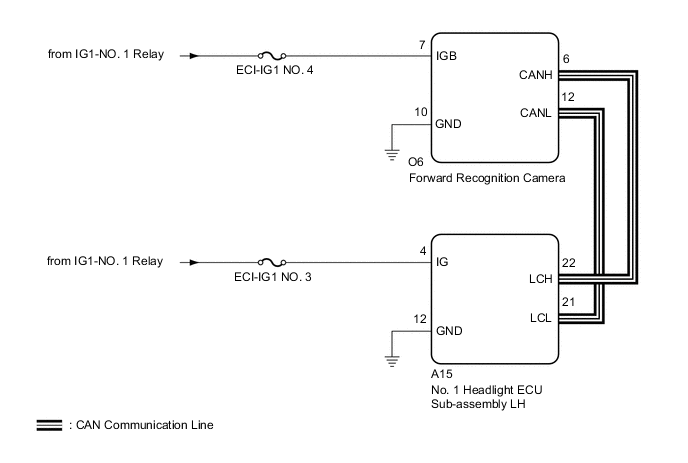
The forward recognition camera communicates with the No. 1 headlight ECU sub-assembly LH via CAN communication. If there is a communication error with the No. 1 headlight ECU sub-assembly LH, the forward recognition camera store DTC U0182.
| DTC No. | Detection Item | DTC Detection Condition | Trouble Area |
|---|---|---|---|
| U0182 | Lost Communication with AFS ECU | 2 seconds after the power switch is turned on (IG), a communication error between the No. 1 headlight ECU sub-assembly LH and the forward recognition camera is detected for approximately 5 seconds or more. |
|
WIRING DIAGRAM
CAUTION / NOTICE / HINT
Note
-
Inspect the fuses for circuits related to this system before performing the following procedure.
-
When replacing the forward recognition camera, always replace it with a new one. If a forward recognition camera which was installed to another vehicle is used, the information stored in the forward recognition camera will not match the information from the vehicle. As a result, a DTC may be stored.
-
If the forward recognition camera has been replaced with a new one, be sure to perform Forward Recognition Camera Learning.
-
After turning the power switch off, waiting time may be required before disconnecting the cable from the negative (-) auxiliary battery terminal. Therefore, make sure to read the disconnecting the cable from the negative (-) auxiliary battery terminal notices before proceeding with work.
PROCEDURE
-
READ VALUE USING GTS (CAN BUS CHECK)
-
Connect the GTS to the DLC3.
-
Turn the power switch on (IG).
-
Turn the GTS on.
-
Enter the following menus: System Select / Can Bus Check.
CAN Bus CheckResult Result Proceed to All of the ECUs and sensors that are currently connected to the CAN communication system are displayed A None of the ECUs and sensors that are currently connected to the CAN communication system are displayed, or some of them are not displayed B
B 
GO TO CAN COMMUNICATION SYSTEM Click here
A 
-
-
CHECK FOR DTCs (CAN COMMUNICATION DTC OUTPUT)
Tech Tips
When pre-crash safety system DTC U1002 is output, check that the local bus is functioning normally by performing the diagnostic procedure for U1002.
-
Check for DTCs.
Body Electrical > Pre-Crash 2 > Trouble CodesResult Result Proceed to DTC U1002 is not output A DTC U1002 is output B
B
GO TO PRE-CRASH SAFETY SYSTEM Click here
A
-
-
CHECK CAN BUS LINE
Tech Tips
If the result is not as specified, a malfunction in a CAN communication line is suspected.
-
Turn the power switch off.
-
Disconnect the cable from the negative (-) auxiliary battery terminal.
-
Disconnect the O6 forward recognition camera connector.
-
Disconnect the A15 No. 1 headlight ECU sub-assembly LH connector.
-
Measure the resistance according to the value(s) in the table below.
Standard Resistance Tester Connection Condition Specified Condition O6-6 (CANH) - A15-22 (LCH) Always Below 1 Ω O6-12 (CANL) - A15-21 (LCL) Always Below 1 Ω -
Connect the A15 No. 1 headlight ECU sub-assembly LH connector.
-
Connect the O6 forward recognition camera connector.
Result Proceed to OK NG
NG
REPAIR OR REPLACE HARNESS OR CONNECTOR
OK
-
-
CHECK POWER SOURCE CIRCUIT (NO. 1 HEADLIGHT ECU SUB-ASSEMBLY LH)
-
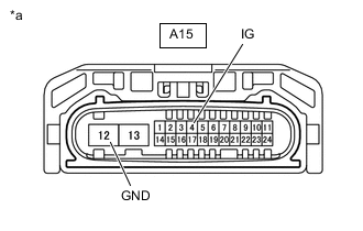
*a Front view of wire harness connector
(to No. 1 Headlight ECU Sub-assembly LH)
Disconnect the A15 No. 1 headlight ECU sub-assembly LH connector.
-
Turn the power switch on (IG).
-
Measure the voltage according to the value(s) in the table below.
Standard Voltage Tester Connection Condition Specified Condition A15-4 (IG) - Body ground Power switch on (IG) 11 to 14 V -
Turn the power switch off.
-
Measure the resistance according to the value(s) in the table below.
Standard Resistance Tester Connection Condition Specified Condition A15-12 (GND) - Body ground Always Below 1 Ω -
Reconnect the A15 No. 1 headlight ECU sub-assembly LH connector.
Result Proceed to OK NG
NG
REPAIR OR REPLACE HARNESS OR CONNECTOR (POWER SOURCE CIRCUIT)
OK
-
-
REPLACE NO. 1 HEADLIGHT ECU SUB-ASSEMBLY LH
-
Replace the No. 1 headlight ECU sub-assembly LH.
Result Proceed to NEXT
NEXT
-
-
CHECK FOR DTCs (FORWARD RECOGNITION CAMERA SYSTEM)
-
Clear the DTCs.
Chassis > Front Recognition Camera > Clear DTCs -
Perform the following procedure.
Tech Tips
If the following procedure is not performed, the previously output DTC cannot be detected.
-
Turn the power switch on (IG) and wait 7 seconds or more.
-
-
Check for DTCs.
Chassis > Front Recognition Camera > Trouble CodesResult Result Proceed to DTC U0182 is not output A DTC U0182 is output B
A
END (NO. 1 HEADLIGHT ECU SUB-ASSEMBLY LH WAS DEFECTIVE)
B
REPLACE FORWARD RECOGNITION CAMERA Click here
-