SFI SYSTEM(w/ Canister Pump Module), Diagnostic DTC:P032515
| DTC Code | DTC Name |
|---|---|
| P032515 | Knock Sensor 1 Bank 1 or Single Sensor Circuit Short to Battery or Open |
DESCRIPTION
Refer to DTC P032511.
Tech Tips
When DTC P032515 is stored, the ECM enters fail-safe mode. During fail-safe mode, the ignition timing is delayed to its maximum retardation. Fail-safe mode continues until the power switch is turned off.
| DTC No. | Detection Item | DTC Detection Condition | Trouble Area | MIL | Memory | Note |
|---|---|---|---|---|---|---|
| P032515 | Knock Sensor 1 Bank 1 or Single Sensor Circuit Short to Battery or Open | The knock control sensor output voltage is higher than 4.5 V for 1 second or more (1 trip detection logic). |
|
Comes on | DTC stored | SAE Code: P0328 |
Reference: Inspection using an oscilloscope.
MONITOR DESCRIPTION
If the output voltage transmitted by the knock control sensor remains high for 1 second or more, the ECM interprets this as a malfunction in the sensor circuit, illuminates the MIL and stores this DTC.
MONITOR STRATEGY
| Frequency of Operation | Continuous |
CONFIRMATION DRIVING PATTERN
-
Connect the GTS to the DLC3.
-
Turn the power switch on (IG).
-
Turn the GTS on.
-
Clear the DTCs (even if no DTCs are stored, perform the clear DTC procedure).
-
Turn the power switch off and wait for at least 30 seconds.
-
Turn the power switch on (IG).
-
Turn the GTS on.
-
Put the engine in Inspection Mode (Maintenance Mode).
-
Start the engine and wait 5 minutes.
-
Enter the following menus: Powertrain / Engine / Trouble Codes.
-
Read the pending DTCs.
Tech Tips
-
If a pending DTC is output, the system is malfunctioning.
-
If a pending DTC is not output, perform the following procedure.
-
-
Enter the following menus: Powertrain / Engine / Utility / All Readiness.
-
Input the DTC: P032515.
-
Check the DTC judgment result.
GTS Display Description NORMAL
-
DTC judgment completed
-
System normal
ABNORMAL
-
DTC judgment completed
-
System abnormal
INCOMPLETE
-
DTC judgment not completed
-
Perform driving pattern after confirming DTC enabling conditions
N/A
-
Unable to perform DTC judgment
-
Number of DTCs which do not fulfill DTC preconditions has reached ECU memory limit
Tech Tips
-
If the judgment result is NORMAL, the system is normal.
-
If the judgment result is ABNORMAL, the system is malfunctioning.
-
If the judgment result is INCOMPLETE or N/A, idle the engine for 5 minutes and check the DTC judgment result again.
-
CAUTION / NOTICE / HINT
Note
-
Vehicle Control History may be stored in the hybrid vehicle control ECU if the engine is malfunctioning. Certain vehicle condition information is recorded when Vehicle Control History is stored. Reading the vehicle conditions recorded in both the freeze frame data and Vehicle Control History can be useful for troubleshooting.
(Select Powertrain in Health Check and then check the time stamp data.)
-
If any "Engine Malfunction" Vehicle Control History item has been stored in the hybrid vehicle control ECU, make sure to clear it. However, as all Vehicle Control History items are cleared simultaneously, if any Vehicle Control History items other than "Engine Malfunction" are stored, make sure to perform any troubleshooting for them before clearing Vehicle Control History.
Tech Tips
Read freeze frame data using the GTS. The ECM records vehicle and driving condition information as freeze frame data the moment a DTC is stored. When troubleshooting, freeze frame data can help determine if the vehicle was moving or stationary, if the engine was warmed up or not, if the air fuel ratio was lean or rich, and other data from the time the malfunction occurred.
PROCEDURE
-
CHECK TERMINAL VOLTAGE (POWER SOURCE OF KNOCK CONTROL SENSOR)
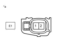
*a Front view of wire harness connector
(to Knock Control Sensor)
-
Disconnect the knock control sensor connector.
-
Turn the power switch on (IG).
-
Measure the voltage according to the value(s) in the table below.
Standard Voltage Tester Connection Condition Specified Condition E1-2 - E1-1 Power switch on (IG) 4.5 to 5.5 V Result Proceed to OK NG
NG 
CHECK HARNESS AND CONNECTOR (KNOCK CONTROL SENSOR - ECM) Click here
OK 
-
-
INSPECT KNOCK CONTROL SENSOR
-
Inspect the knock control sensor.
Result Proceed to OK NG
OK
GO TO STEP 4 Click here
NG 
REPLACE KNOCK CONTROL SENSOR Click here
-
-
CHECK HARNESS AND CONNECTOR (KNOCK CONTROL SENSOR - ECM)
-
Disconnect the knock control sensor connector.
-
Disconnect the ECM connector.
-
Measure the resistance according to the value(s) in the table below.
Standard Resistance Tester Connection Condition Specified Condition E1-2 - C31-122 (KNK1) Always Below 1 Ω E1-1 - C31-121 (EKNK) Always Below 1 Ω E1-2 or C31-122 (KNK1) - Other terminals Always 10 kΩ or higher Result Proceed to OK NG
NG
REPAIR OR REPLACE HARNESS OR CONNECTOR
OK
-
-
CLEAR DTC
-
Connect the GTS to the DLC3.
-
Turn the power switch on (IG).
-
Turn the GTS on.
-
Clear the DTCs.
Powertrain > Engine > Clear DTCs -
Turn the power switch off and wait for at least 30 seconds.
Result Proceed to NEXT
NEXT
-
-
CHECK WHETHER DTC OUTPUT RECURS (DTC P032515)
-
Drive the vehicle in accordance with the driving pattern described in Confirmation Driving Pattern.
-
Enter the following menus: Powertrain / Engine / Trouble Codes.
-
Read the DTCs.
Powertrain > Engine > Trouble CodesResult Result Proceed to DTCs are not output A DTC P032515 is output B
A
CHECK FOR INTERMITTENT PROBLEMS Click here
B
REPLACE ECM Click here
-