SFI SYSTEM(w/ Canister Pump Module), Diagnostic DTC:P10AA00, P219A00, P219C00, P219D00, P219E00, P219F00
| DTC Code | DTC Name |
|---|---|
| P10AA00 | Clogged EGR Port Imbalance Bank1 |
| P219A00 | Bank 1 Air-Fuel Ratio Imbalance |
| P219C00 | Cylinder 1 Air-Fuel Ratio Imbalance |
| P219D00 | Cylinder 2 Air-Fuel Ratio Imbalance |
| P219E00 | Cylinder 3 Air-Fuel Ratio Imbalance |
| P219F00 | Cylinder 4 Air-Fuel Ratio Imbalance |
DESCRIPTION
Refer to DTC P030000.
Refer to DTC P04019C.
Refer to DTC P21951D.
| DTC No. | Detection Item | DTC Detection Condition | Trouble Area | MIL | Memory | Note |
|---|---|---|---|---|---|---|
| P10AA00 | Clogged EGR Port Imbalance Bank1 | The difference in the air fuel ratios between the cylinders exceeds the threshold when the EGR valve is open (2 trip detection logic). | Intake manifold | Comes on | DTC stored | SAE Code: P10AA |
| P219A00 | Bank 1 Air-Fuel Ratio Imbalance | The difference in air fuel ratios between the cylinders exceeds the threshold (2 trip detection logic). |
|
Comes on | DTC stored | SAE Code: P219A |
| P219C00 | Cylinder 1 Air-Fuel Ratio Imbalance | The difference in air fuel ratios between the cylinders exceeds the threshold (2 trip detection logic). |
|
Comes on | DTC stored | SAE Code: P219C |
| P219D00 | Cylinder 2 Air-Fuel Ratio Imbalance | The difference in air fuel ratios between the cylinders exceeds the threshold (2 trip detection logic). |
|
Comes on | DTC stored | SAE Code: P219D |
| P219E00 | Cylinder 3 Air-Fuel Ratio Imbalance | The difference in air fuel ratios between the cylinders exceeds the threshold (2 trip detection logic). |
|
Comes on | DTC stored | SAE Code: P219E |
| P219F00 | Cylinder 4 Air-Fuel Ratio Imbalance | The difference in air fuel ratios between the cylinders exceeds the threshold (2 trip detection logic). |
|
Comes on | DTC stored | SAE Code: P219F |
MONITOR DESCRIPTION
- Fuel System Air Fuel Ratio Cylinder Imbalance Monitor
The ECM uses the air fuel ratio sensor, crankshaft position sensor and EGR valve assembly to monitor the difference in air fuel ratios between the cylinders caused by differences in fuel injection volume between the cylinders, leakage in the intake or exhaust system, etc.
When the air fuel ratios of the cylinders are lean or rich with respect to each other, the ECM determines that there is a malfunction, illuminates the MIL and stores a DTC.
- EGR Port Clogged Monitoring Method: P10AA00 is stored primarily when a rich side imbalance for clogged EGR port is detected.
By comparing the air fuel ratio when EGR valve is open and closed, a clog in an EGR port can be detected. If an EGR port is clogged when the EGR valve is open, the ECM will store a DTC.
- Air Fuel Ratio Sensor Monitoring Method: P219A00 is stored primarily when a rich side imbalance is detected.
When the system detects a difference in air fuel ratios between the cylinders due to fluctuation in the air fuel ratio sensor output over 1 engine cycle (2 crankshaft revolutions), the ECM determines that there is a malfunction.
- Crankshaft Position Sensor Monitoring Method: P219C00, P219D00, P219E00 and/or P219F00 are stored primarily when a lean side imbalance is detected.
The system monitors the engine speed variation and when the variation becomes large, the ECM determines that there is a difference in air fuel ratios between the cylinders, which it determines to be a malfunction.
MONITOR STRATEGY
| Required Sensors/Components | EGR valve assembly Air fuel ratio sensor Crankshaft position sensor |
| Frequency of Operation | Once per driving cycle |
CONFIRMATION DRIVING PATTERN
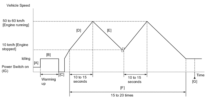
- P10AA00
-
Connect the GTS to the DLC3.
-
Turn the power switch on (IG).
-
Turn the GTS on.
-
Clear the DTCs (even if no DTCs are stored, perform the clear DTC procedure).
-
Turn the power switch off and wait for at least 30 seconds.
-
Turn the power switch on (IG) [A].
-
Turn the GTS on.
-
Put the engine in Inspection Mode (Maintenance Mode).
-
Start the engine and warm it up until the engine coolant temperature is 75°C (167°F) or higher [B].
-
Turn the power switch off. [C]
-
Turn the power switch on (READY).
-
Press the EV/HV mode selection switch to select HV mode.
-
Start the engine by depressing the accelerator pedal approximately 40% and accelerating the vehicle from 10 km/h (6 mph) to a speed between 50 and 60 km/h (31 to 37 mph) in 10 to 15 seconds [D].
CAUTION:
When performing the confirmation driving pattern, obey all speed limits and traffic laws.
Tech Tips
If the engine does not start, further depress the accelerator pedal.
-
Decelerate the vehicle to less than 10 km/h (6 mph) and allow the engine to stop [E].
CAUTION:
When performing the confirmation driving pattern, obey all speed limits and traffic laws.
Tech Tips
The vehicle can be decelerated by any method.
-
Repeat steps [D] and [E] above 15 to 20 times [F].
-
Enter the following menus: Powertrain / Engine / Trouble Codes [G].
-
Read the pending DTCs.
Tech Tips
-
If a pending DTC is output, the system is malfunctioning.
-
If a pending DTC is not output, perform the following procedure.
-
-
Enter the following menus: Powertrain / Engine / Utility / All Readiness.
-
Input the DTC: P10AA00.
-
Check the DTC judgment result.
GTS Display Description NORMAL
-
DTC judgment completed
-
System normal
ABNORMAL
-
DTC judgment completed
-
System abnormal
INCOMPLETE
-
DTC judgment not completed
-
Perform driving pattern after confirming DTC enabling conditions
N/A
-
Unable to perform DTC judgment
-
Number of DTCs which do not fulfill DTC preconditions has reached ECU memory limit
Tech Tips
-
If the judgment result is NORMAL, the system is normal.
-
If the judgment result is ABNORMAL, the system is malfunctioning.
-
If the judgment result is INCOMPLETE, perform the confirmation driving pattern and check the judgment result again.
-
If the judgment result is N/A, perform the following procedure.
-
-
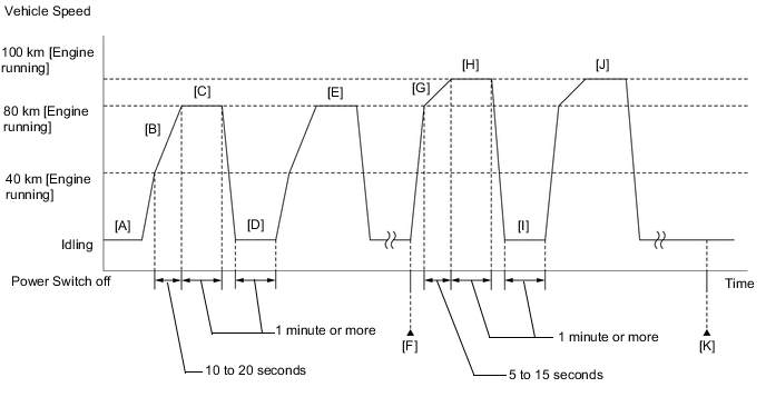
- P219A00, P219C00, P219D00, P219E00 and P219F00
-
Connect the GTS to the DLC3.
-
Turn the power switch on (IG).
-
Turn the GTS on.
-
Put the engine in Inspection Mode (Maintenance Mode).
-
Start the engine and warm it up until the engine coolant temperature is 75°C (167°F) or higher [A].
-
Clear the DTCs (even if no DTCs are stored, perform the clear DTC procedure).
Note
Use the GTS to clear the DTCs. (Do not disconnect the cable from negative (-) auxiliary battery terminal to clear the DTCs.)
-
Press the EV/HV mode selection switch to select HV mode.
-
With the engine running, drive the vehicle at 40 km/h (25 mph) or higher.
CAUTION:
When performing the confirmation driving pattern, obey all speed limits and traffic laws.
Tech Tips
If the engine stops, further depress the accelerator pedal to restart the engine.
-
With the engine running, gradually accelerate the vehicle from 40 km/h (25 mph) to 80 km/h (50 mph) taking approximately 10 to 20 seconds [B].
Tech Tips
-
Refer to engine load and engine speed in Typical Enabling Conditions, and then accelerate the vehicle to 80 km/h (50 mph).
-
If the engine stops, further depress the accelerator pedal to restart the engine.
-
-
With the engine running, drive the vehicle at 80 km/h (50 mph) or higher for 1 minute or more [C].
CAUTION:
When performing the confirmation driving pattern, obey all speed limits and traffic laws.
Tech Tips
-
Electrical load can be applied while the vehicle is driven.
-
If the engine stops, further depress the accelerator pedal to restart the engine.
-
-
Idle the engine for 1 minute or more [D].
Tech Tips
Perform this step with drive (D) selected.
-
Repeat steps [B] through [D] above at least 3 times [E].
-
Enter the following menus: Powertrain / Engine / Trouble Codes [F].
-
Read the pending DTCs.
Tech Tips
-
If a pending DTC is output, the system is malfunctioning.
-
If a pending DTC is not output, perform the following procedure.
-
-
With the engine running, drive the vehicle at 80 km/h (50 mph).
CAUTION:
When performing the confirmation driving pattern, obey all speed limits and traffic laws.
Tech Tips
If the engine stops, further depress the accelerator pedal to restart the engine.
-
With the engine running, gradually accelerate the vehicle from 80 km/h (50 mph) to 100 km/h (62 mph) taking approximately 5 to 15 seconds [G].
CAUTION:
When performing the confirmation driving pattern, obey all speed limits and traffic laws.
Tech Tips
-
Refer to engine load and engine speed in Typical Enabling Conditions, and then accelerate the vehicle to 100 km/h (62 mph).
-
If the engine stops, further depress the accelerator pedal to restart the engine.
-
-
With the engine running, drive the vehicle at 100 km/h (62 mph) or higher for 1 minute or more [H].
CAUTION:
When performing the confirmation driving pattern, obey all speed limits and traffic laws.
Tech Tips
-
Electrical load can be applied while the vehicle is driven.
-
If the engine stops, further depress the accelerator pedal to restart the engine.
-
-
Idle the engine for 1 minute or more [I].
Tech Tips
Perform this step with drive (D) selected.
-
Repeat steps [G] through [I] above at least 2 times [J].
-
Enter the following menus: Powertrain / Engine / Trouble Codes [K].
-
Read the pending DTCs.
Tech Tips
-
If a pending DTC is output, the system is malfunctioning.
-
If a pending DTC is not output, perform the following procedure.
-
-
Enter the following menus: Powertrain / Engine / Utility / All Readiness.
-
Input the DTC: P219A00, P219C00, P219D00, P219E00 or P219F00.
-
Check the DTC judgment result.
GTS Display Description NORMAL
-
DTC judgment completed
-
System normal
ABNORMAL
-
DTC judgment completed
-
System abnormal
INCOMPLETE
-
DTC judgment not completed
-
Perform driving pattern after confirming DTC enabling conditions
N/A
-
Unable to perform DTC judgment
-
Number of DTCs which do not fulfill DTC preconditions has reached ECU memory limit
Tech Tips
-
If the judgment result is NORMAL, the system is normal.
-
If the judgment result is ABNORMAL, the system is malfunctioning.
-
If the judgment result is INCOMPLETE, perform the confirmation driving pattern and check the judgment result again.
-
If the judgment result is N/A, perform the following procedure.
-
-
CAUTION / NOTICE / HINT
Tech Tips
-
Sensor 1 refers to the sensor closest to the engine assembly.
-
Sensor 2 refers to the sensor farthest away from the engine assembly.
-
When any air fuel ratio imbalance is detected, the ECM will perform air fuel ratio feedback control to make the air fuel ratio close to the stoichiometric air fuel ratio. This may result in an air fuel ratio imbalance of normal cylinders and DTCs may be stored.
-
Read freeze frame data using the GTS. The ECM records vehicle and driving condition information as freeze frame data the moment a DTC is stored. When troubleshooting, freeze frame data can help determine if the vehicle was moving or stationary, if the engine was warmed up or not, if the air fuel ratio was lean or rich, and other data from the time the malfunction occurred.
PROCEDURE
-
CHECK ANY OTHER DTCS OUTPUT
-
Connect the GTS to the DLC3.
-
Turn the power switch on (IG).
-
Turn the GTS on.
-
Enter the following menus: Powertrain / Engine / Trouble Codes.
-
Read the DTCs.
Powertrain > Engine > Trouble CodesResult Result Proceed to DTC P10AA00, P219A00, P219C00, P219D00, P219E00 and/or P219F00 is output A DTC P10AA00, P219A00, P219C00, P219D00, P219E00 and/or P219F00 and other DTCs are output B Tech Tips
If any DTCs other than DTC P10AA00, P219A00, P219C00, P219D00, P219E00 and/or P219F00 are output, troubleshoot those DTCs first.
B 
GO TO DTC CHART Click here
A 
-
-
READ VALUE USING GTS (FREEZE FRAME DATA)
-
Connect the GTS to the DLC3.
-
Turn the power switch on (IG).
-
Turn the GTS on.
-
Using the GTS, confirm the vehicle conditions recorded in the freeze frame data which were present when the DTC was stored.
-
Vehicle Speed
-
Engine Speed
-
Calculate Load
-
Short FT Bank 1
-
Long FT Bank 1
-
Misfire Count Cylinder #1 to #4
Freeze Frame Data Items for DTC P10AA00, P219A00, P219C00, P219D00, P219E00 and/or P219F00:
Tech Tips
When the sum of Short FT Bank 1 and Long FT Bank 1 is positive, the engine is running lean, and when the sum is negative, the engine is running rich.
Air Fuel Ratio Sensor Monitoring Method (P219A00) Crankshaft Position Sensor Monitoring Method (P219C00, P219D00, P219E00 and P219F00) EGR Port Clogged Monitoring Method (P10AA00) Note - - DTC is output Detected by EGR Port Clogged Monitoring Method.*1 DTC is output DTC is output (Only one DTC relating to a single cylinder is output) DTC is not output Malfunctioning of cylinders detected by Crankshaft Position Sensor Monitoring Method is primarily suspected DTC is output DTCs are output (Multiple DTCs relating to multiple cylinders are output) DTC is not output Malfunctioning of cylinders except ones detected by Crankshaft Position Sensor Monitoring Method is primarily suspected.*2 DTC is not output DTCs are output DTC is not output Malfunctioning of cylinders detected by Crankshaft Position Sensor Monitoring Method is primarily suspected. DTC is output DTCs are not output DTC is not output Malfunctioning of the bank detected by Air Fuel Ratio Sensor Monitoring Method is primarily suspected. *1: Even if other DTCs are output, it is likely that an EGR port is clogged.
*2: When any air fuel ratio imbalance is detected, the ECM will perform air fuel ratio feedback control to make the air fuel ratio close to the stoichiometric air fuel ratio. This may result in an air fuel ratio imbalance of normal cylinders and DTCs may be stored.
Result Proceed to NEXT -
NEXT
-
-
READ OUTPUT DTC
-
Connect the GTS to the DLC3.
-
Turn the power switch on (IG).
-
Turn the GTS on.
-
Put the engine in Inspection Mode (Maintenance Mode).
Powertrain > Hybrid Control > UtilityTester Display Inspection Mode -
Drive the vehicle in accordance with Confirmation Driving Pattern.
Tech Tips
-
If any misfire count (Misfire Count Cylinder #1 to #4) increases while idling or driving the vehicle, proceed to step 7.
-
Perform inspections while focusing on the cylinder whose misfire count has increased.
-
Perform the confirmation driving patterns for both DTC P10AA00 and P219A00.
-
-
Enter the following menus: Powertrain / Engine / Trouble Codes.
-
Read the DTCs.
Powertrain > Engine > Trouble CodesResult Result Proceed to DTC P10AA00 is output A DTC P219A00 is output B DTC P219A00 and P219C00, P219D00 or P219E00 are output C DTC P219C00, P219D00, P219E00 and/or P219F00 is output
B 
PERFORM ACTIVE TEST USING GTS (CONTROL THE INJECTION VOLUME) Click here
C
GO TO STEP 7 Click here
A
-
-
REPLACE INTAKE MANIFOLD
-
Replace the intake manifold.
Result Proceed to NEXT
NEXT
GO TO STEP 14 Click here
-
-
PERFORM ACTIVE TEST USING GTS (CONTROL THE INJECTION VOLUME)
-
Connect the GTS to the DLC3.
-
Turn the power switch on (IG).
-
Turn the GTS on.
-
Put the engine in Inspection Mode (Maintenance Mode).
Powertrain > Hybrid Control > UtilityTester Display Inspection Mode -
Start the engine and warm it up.
Tech Tips
The A/C switch and all accessories should be off and park (P) or neutral (N) should be selected.
-
Enter the following menus: Powertrain / Engine / Active Test / Control the Injection Volume / Data List / Misfire Count Cylinder #1 to #4.
Tech Tips
When the "Control the Injection Volume" Active Test is selected (injection volume is 0%), if a misfire count increases, proceed to step 7 (Check Intake System).
Powertrain > Engine > Active TestActive Test Display Control the Injection Volume Data List Display Misfire Count Cylinder #1 Misfire Count Cylinder #2 Misfire Count Cylinder #3 Misfire Count Cylinder #4 -
According to the display on the GTS, perform the Active Test with the engine idling.
-
Check the misfire counts (Misfire Count Cylinder #1 to #4) while decreasing the injection volume in 5% increments.
Result The cylinder whose misfire count has not increased can be assumed to be running rich. Therefore, perform inspections while focusing on that cylinder. Result Proceed to NEXT
NEXT
-
-
CHECK FOR EXHAUST GAS LEAK
-
Check for exhaust gas leaks.
OK No gas leaks in exhaust system. Tech Tips
Perform "Inspection After Repair" after repairing or replacing the exhaust system.
Result Proceed to OK NG
NG
REPAIR OR REPLACE EXHAUST SYSTEM
OK
-
-
CHECK INTAKE SYSTEM
-
Check the intake system for vacuum leaks.
OK No leaks from the intake system. Tech Tips
Perform "Inspection After Repair" after repairing or replacing the intake system.
Result Proceed to OK NG
NG
REPAIR OR REPLACE INTAKE SYSTEM
OK
-
-
INSPECT SPARK PLUG
-
Inspect the spark plug of the cylinder causing the imbalance.
Result Proceed to OK NG
NG
REPLACE SPARK PLUG Click here
OK
-
-
CHECK FOR SPARK (SPARK TEST)
-
Perform a spark test.
Tech Tips
-
If the result of the spark test is normal, proceed to the next step.
-
Perform "Inspection After Repair" after repairing or replacing the ignition system.
Result Proceed to NEXT -
NEXT
-
-
CHECK CYLINDER COMPRESSION PRESSURE
-
Measure the cylinder compression pressure of the misfiring cylinder.
Tech Tips
Perform "Inspection After Repair" after repairing or replacing the engine assembly.
Result Proceed to OK NG
NG
CHECK ENGINE TO DETERMINE CAUSE OF LOW COMPRESSION
OK
-
-
CHECK TERMINAL VOLTAGE (POWER SOURCE OF FUEL INJECTOR ASSEMBLY)
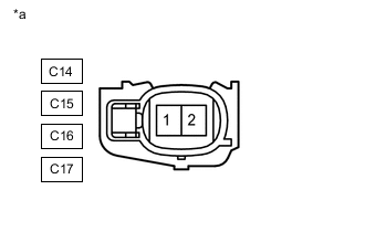
*a Front view of wire harness connector
(to Fuel Injector Assembly)
-
Disconnect the fuel injector assembly connector.
-
Turn the power switch on (IG).
-
Measure the voltage according to the value(s) in the table below.
Standard Voltage Tester Connection Condition Specified Condition C14-1 - Body ground Power switch on (IG) 11 to 14 V C15-1 - Body ground Power switch on (IG) 11 to 14 V C16-1 - Body ground Power switch on (IG) 11 to 14 V C17-1 - Body ground Power switch on (IG) 11 to 14 V Result Proceed to OK NG
NG
CHECK FUEL INJECTOR CIRCUIT Click here
OK
-
-
CHECK FUEL INJECTOR ASSEMBLY OF CYLINDER CAUSING IMBALANCE
-
Check the fuel injector assembly injection (whether fuel volume is high or low, and whether injection pattern is poor).
Result Proceed to OK NG
NG
REPLACE FUEL INJECTOR ASSEMBLY Click here
OK
-
-
CHECK FOR CAUSE OF FAILURE
-
If the cause of the problem has not been found even after performing the troubleshooting procedure, perform the inspection below.
-
Check the intake valve for deposits.
Tech Tips
As the DTC may have been stored due to deposits an the intake valve, remove the cylinder head and check the intake valves.
Result Proceed to NEXT
NEXT
-
-
CLEAR DTC
-
Connect the GTS to the DLC3.
-
Turn the power switch on (IG).
-
Turn the GTS on.
-
Clear the DTCs.
Powertrain > Engine > Clear DTCs -
Turn the power switch off and wait for at least 30 seconds.
Result Proceed to NEXT
NEXT
-
-
CONFIRM WHETHER MALFUNCTION HAS BEEN SUCCESSFULLY REPAIRED
-
Drive the vehicle in accordance with the driving pattern described in Confirmation Driving Pattern.
Tech Tips
Perform the appropriate confirmation driving patterns for the DTCs that were output.
-
Enter the following menus: Powertrain / Engine / Trouble Codes.
-
Check for DTCs.
Powertrain > Engine > Trouble CodesOK DTCs are not output. Result Proceed to NEXT
NEXT
END
-