BRAKE FLUID REPLACEMENT
CAUTION / NOTICE / HINT
Note
-
Perform fluid replacement with park (P) selected and the parking brake applied.
-
Perform fluid replacement while maintaining the brake fluid level between the MAX and MIN lines on the brake fluid reservoir.
-
When the No. 2 brake actuator hose (the hose between the brake booster pump assembly and brake master cylinder reservoir assembly) is higher than the fluid level, air enters the hose and brake booster pump assembly while the pump motor is operating and it is difficult to replace brake fluid.
-
When performing fluid replacement, the accumulator pressure drop may cause a buzzer to sound. As this is not a malfunction, continue with the fluid replacement.
-
If fluid replacement is performed, a motor drive permission malfunction or accumulator low pressure DTC may be stored. Clear the DTCs after performing fluid replacement or whenever specified by a procedure.
-
Do not allow brake fluid to contact any painted surface. If brake fluid leaks onto any painted surface, immediately wash it off.
-
When performing fluid replacement, do not continuously operate the pump motor for more than 100 seconds. If the pump motor is operated for more than 100 seconds, release the brake pedal to stop operation of the pump in order to prevent damage to the pump motor.
-
As brake fluid may overflow from the reservoir when brake fluid is released from the accumulator, do not invert and place the brake fluid bottle on the reservoir filler opening.
Tech Tips
There are 2 ways of brake fluid replacement: using the GTS or not using the GTS.
PROCEDURE
-
REPLACE BRAKE FLUID (When Using the GTS)
-
Separate the center No. 1 cowl top ventilator louver. (for LHD, RHD Type A)
Tech Tips
-
Use the same procedure for RHD and LHD vehicles.
-
The procedure listed below is for LHD vehicles.
-
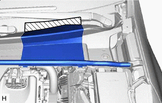

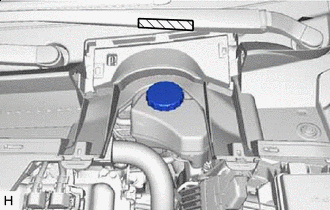
Protective Tape Apply protective tape to the area shown in the illustration.
-
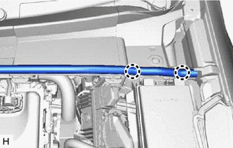
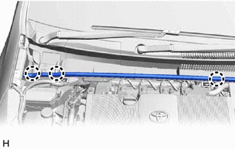
Disengage the 2 claws and separate the hood to cowl top seal from the cowl top ventilator louver.
-
Disengage the 2 claws and 5 guides and separate the center No. 1 cowl top ventilator louver.
-
-
Separate the center No. 1 cowl top ventilator louver. (for RHD Type B)
-
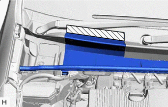
Protective Tape Apply protective tape to the area shown in the illustration.
-
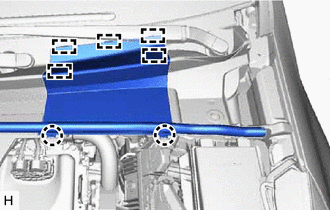
Disengage the 3 claws and separate the hood to cowl top seal from the cowl top ventilator louver.
-
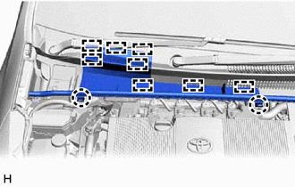
Disengage the 2 claws and 8 guides and separate the center No. 1 cowl top ventilator louver.
-
-
Fill the reservoir with brake fluid.
-
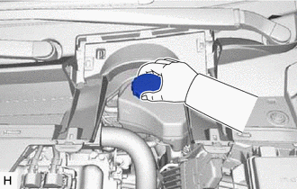
Remove the brake master cylinder reservoir filler cap assembly.
-
Add brake fluid to the reservoir until the fluid level is between the MAX and MIN lines on the brake fluid reservoir.
Brake Fluid SAE J1703 or FMVSS No. 116 DOT3 SAE J1704 or FMVSS No. 116 DOT4
-
-
Replace the brake fluid.
-
Connect the GTS to the DLC3 and turn the power switch on (IG).
-
Turn the GTS on and enter the following menus: Chassis / ABS/VSC/TRC / Utility / Air Bleeding/AHB-R Utility.
Chassis > ABS/VSC/TRC > UtilityTester Display Air Bleeding/AHB-R Utility -
Select "Brake Line Air Bleeding", and replace the brake fluid following the instructions on the GTS.
-
After replacing brake fluid, tighten each bleeder plug.
- Torque:
- Front Disc Brake Bleeder Plug
- 8.3 N*m { 85 kgf*cm, 73 in.*lbf }
- Rear Disc Brake Bleeder Plug
- 11 N*m { 112 kgf*cm, 8 ft.*lbf }
-
-
Install the brake master cylinder reservoir filler cap assembly.
-
Clear the DTCs.
-
Turn the GTS off then turn the power switch off.
-
Inspect for brake fluid leaks.
-
Install the center No. 1 cowl top ventilator louver. (for LHD, RHD Type A)
-
Engage the 2 claws and 5 guides to install the center No. 1 cowl top ventilator louver.
-
Engage the 2 claws to install the hood to cowl top seal to the cowl top ventilator louver.
-
Remove the protective tape.
-
-
Install the center No. 1 cowl top ventilator louver. (for RHD Type B)
-
Engage the 2 claws and 8 guides to install the center No. 1 cowl top ventilator louver.
-
Engage the 3 claws to install the hood to cowl top seal to the cowl top ventilator louver.
-
Remove the protective tape.
-
-
-
REPLACE BRAKE FLUID (When Not Using the GTS)
Note
-
Performing the following procedure enters ECB (Electronically Controlled Brake system) Invalid Mode without using the GTS.
-
ECB (Electronically Controlled Brake system) Invalid Mode allows the brake fluid to be replaced without using the GTS.
-
The brake warning light blinks (yellow) to indicate that ECB (Electronically Controlled Brake system) Invalid Mode is selected.
-
Be sure to confirm that the brake warning light is blinking (yellow) throughout the brake fluid replacement procedure.
-
If any of the following conditions are met, ECB (Electronically Controlled Brake system) Invalid Mode is canceled and the brake warning light (yellow) turns off. Do not allow ECB (Electronically Controlled Brake system) Invalid Mode to be canceled while replacing brake fluid or DTCs may be stored.
A shift state other than park (P) is selected. The power switch is turned on (READY). The power switch is turned off. The parking brake is released. The vehicle speed is more than 0 km/h (0 mph). -
Do not rotate any brake disc while ECB (Electronically Controlled Brake system) Invalid Mode is selected.
-
Although the brake warning light will blink (yellow) and a buzzer will sound while performing fluid replacement, this is not a malfunction.
-
Remove all 4 wheels.
-
Enter ECB (Electronically Controlled Brake system) Invalid Mode.
-
Perform the procedure listed below within 1 minute.
-
Turn the power switch on (IG) with park (P) selected and the parking brake applied.
-
Select neutral (N) and then depress the brake pedal more than 8 times within 5 seconds.
-
Push the P position switch and then depress the brake pedal more than 8 times within 5 seconds.
-
Select neutral (N) and then depress the brake pedal more than 8 times within 5 seconds.
-
Push the P position switch.
-
-
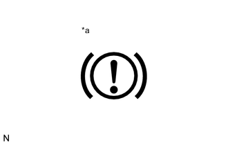
*a Brake Warning Light (Yellow) Check that the brake warning light is blinking (yellow).
-
-
Separate the center No. 1 cowl top ventilator louver. (for LHD, RHD Type A)
Tech Tips
-
Use the same procedure for RHD and LHD vehicles.
-
The procedure listed below is for LHD vehicles.
-
Protective Tape Apply protective tape to the area shown in the illustration.
-
Disengage the 2 claws and separate the hood to cowl top seal from the cowl top ventilator louver.
-
Disengage the 2 claws and 5 guides and separate the center No. 1 cowl top ventilator louver.
-
-
Separate the center No. 1 cowl top ventilator louver. (for RHD Type B)
-
Protective Tape Apply protective tape to the area shown in the illustration.
-
Disengage the 3 claws and separate the hood to cowl top seal from the cowl top ventilator louver.
-
Disengage the 2 claws and 8 guides and separate the center No. 1 cowl top ventilator louver.
-
-
Fill the reservoir with brake fluid.
-
Remove the brake master cylinder reservoir filler cap assembly.
-
Add brake fluid to the reservoir until the fluid level is between the MAX and MIN lines on the brake fluid reservoir.
Brake Fluid SAE J1703 or FMVSS No. 116 DOT3 SAE J1704 or FMVSS No. 116 DOT4
-
-
Replace the brake fluid.
Tech Tips
-
When replacing the brake fluid using vacuum, the brake fluid bottle can be inverted and placed on the reservoir filler opening.
-
Protective Tape Apply protective tape to the area shown in the illustration when placing the brake fluid bottle.
-
Connect a vinyl tube to the bleeder plug of the front disc brake cylinder assembly RH.
-
Depress the brake pedal several times, and then loosen the bleeder plug with the pedal depressed.*1
-
When fluid stops coming out, tighten the bleeder plug, and then release the brake pedal.*2
-
Repeat steps *1 and *2 until new brake fluid comes out.
-
Tighten the bleeder plug completely.
- Torque:
- 8.3 N*m { 85 kgf*cm, 73 in.*lbf }
-
Replace brake fluid from the front disc brake cylinder assembly LH using the same procedure as for the RH side.
-
Connect a vinyl tube to the bleeder plug of the rear disc brake cylinder assembly LH.
-
Depress the brake pedal several times, and then loosen the bleeder plug with the pedal depressed.*3
-
When fluid stops coming out, tighten the bleeder plug, and then release the brake pedal.*4
-
Repeat steps *3 and *4 until new brake fluid comes out.
-
Tighten the bleeder plug completely.
- Torque:
- 11 N*m { 112 kgf*cm, 8 ft.*lbf }
-
Replace brake fluid from the rear disc brake cylinder assembly RH using the same procedure as for the LH side.
-
Turn the power switch off.
-
-
Inspect for brake fluid leaks.
-
Adjust the brake fluid level in the reservoir.
-
Install the brake master cylinder reservoir filler cap assembly.
-
Install the 4 wheels.
-
Install the center No. 1 cowl top ventilator louver. (for LHD, RHD Type A)
-
Engage the 2 claws and 5 guides to install the center No. 1 cowl top ventilator louver.
-
Engage the 2 claws to install the hood to cowl top seal to the cowl top ventilator louver.
-
Remove the protective tape.
-
-
Install the center No. 1 cowl top ventilator louver. (for RHD Type B)
-
Engage the 2 claws and 8 guides to install the center No. 1 cowl top ventilator louver.
-
Engage the 3 claws to install the hood to cowl top seal to the cowl top ventilator louver.
-
Remove the protective tape.
-
-