COOLING FAN MOTOR INSTALLATION
PROCEDURE
-
INSTALL COOLING FAN MOTOR LH
-
Install the cooling fan motor LH with the 3 screws.
- Torque:
- 3.9 N*m { 40 kgf*cm, 35 in.*lbf }
-
-
INSTALL COOLING FAN MOTOR RH
-
Install the cooling fan motor RH with the 3 screws.
- Torque:
- 3.9 N*m { 40 kgf*cm, 35 in.*lbf }
-
-
INSTALL FAN LH
Note
Do not reverse the position of the fan LH and fan RH when installing them. Doing so may damage the parts.
-
Install the fan LH with the 3 screws.
- Torque:
- 3.9 N*m { 40 kgf*cm, 35 in.*lbf }
-
-
INSTALL FAN RH
Note
Do not reverse the position of the fan LH and fan RH when installing them. Doing so may damage the parts.
-
Install the fan RH with the 3 screws.
- Torque:
- 3.9 N*m { 40 kgf*cm, 35 in.*lbf }
-
-
INSTALL FAN ASSEMBLY
-
Engage the 2 guides.
-
Engage the 2 claws to install the fan assembly to the radiator assembly.
Note
Do not damage the radiator assembly when installing the fan assembly.
-
-
INSTALL NO. 2 RADIATOR AIR GUIDE
-
Engage the 5 claws to install a new No. 2 radiator air guide to the radiator assembly.
-
-
CONNECT INLET HYBRID RADIATOR HOSE
-
Connect the inlet hybrid radiator hose and slide the clip to secure it.
-
Engage the clamp to connect the inlet hybrid radiator hose to the fan shroud.
-
-
CONNECT NO. 2 RADIATOR HOSE
-
Connect the No. 2 radiator hose and slide the clip to secure it.
-
-
CONNECT NO. 2 WATER BY-PASS HOSE
-
Engage the 4 clamps to connect the No. 2 water by-pass hose to the fan shroud.
-
Connect the No. 2 water by-pass hose and slide the clip to secure it.
-
-
CONNECT NO. 1 WATER BY-PASS HOSE
-
Connect the No. 1 water by-pass hose and slide the clip to secure it.
-
-
INSTALL INVERTER RESERVE TANK ASSEMBLY
-
Engage the clamp to connect the inlet hybrid water pump hose to the fan shroud.
-
Engage the 2 claws to install the inverter reserve tank assembly to the fan shroud.
-
-
CONNECT INLET NO. 1 INVERTER COOLING HOSE
-
Connect the inlet No. 1 inverter cooling hose and slide the clip to secure it.
-
Engage the 2 clamps to connect the inlet No. 1 inverter cooling hose to the fan shroud and inverter reserve tank assembly.
-
Engage the 3 clamps to connect the wire harness to the fan shroud.
-
-
CONNECT OUTLET NO. 1 INVERTER COOLING HOSE
-
Connect the outlet No. 1 inverter cooling hose and slide the clip to secure it.
-
-
INSTALL RADIATOR SUPPORT CUSHION
-
Install the 2 radiator support cushions to the radiator assembly.
-
-
INSTALL UPPER RADIATOR SUPPORT SUB-ASSEMBLY
-
Temporarily install the upper radiator support sub-assembly with the 5 bolts.
-
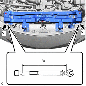
*a Torque Wrench Fulcrum Length Using a 10 mm union nut wrench, fully tighten the bolt (A).
- Torque:
- Specified tightening torque
- 12.5 N*m { 127 kgf*cm, 9 ft.*lbf }
Tech Tips
-
Calculate the torque wrench reading when changing the fulcrum length of the torque wrench.
-
When using a 10 mm union nut wrench (fulcrum length of 22 mm (0.866 in.)) + torque wrench (fulcrum length of 162 mm (6.38 in.)): 11 N*m (112 kgf*cm, 8 ft.*lbf)
-
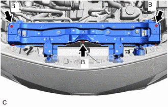
Fully tighten the bolt (B).
- Torque:
- 12.5 N*m { 127 kgf*cm, 9 ft.*lbf }
-
Install the front bumper assembly to the upper radiator support sub-assembly with the 2 bolts.
-
Engage the clamp to connect the hood lock control cable assembly to the upper radiator support sub-assembly.
-
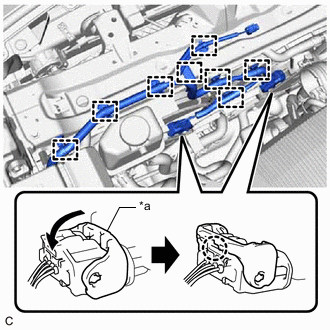
*a Lock Lever Engage the 8 clamps to connect the wire harness to the upper radiator support sub-assembly and fan shroud.
-
Connect the cooling fan motor RH connector and cooling fan motor LH connector and push down the 2 lock levers to engage the 2 claws as shown in the illustration.
Note
-
When connecting the cooling fan motor RH connector and cooling fan motor LH connector, make sure that the connecting parts of the cooling fan motor RH connector and cooling fan motor LH connector are free of dirt, water or other foreign matter.
-
Be sure to securely connect the cooling fan motor RH connector and cooling fan motor LH connector.
-
-
w/ Vehicle Approaching Speaker Assembly:
-
Connect the vehicle approaching speaker assembly connector.
-
-
Connect the 2 horn connectors.
-
-
INSTALL HOOD LOCK ASSEMBLY
-
INSTALL AIR CLEANER CASE SUB-ASSEMBLY
-
INSTALL AIR CLEANER FILTER ELEMENT SUB-ASSEMBLY
-
INSTALL AIR CLEANER CAP SUB-ASSEMBLY
-
INSTALL INLET NO. 2 AIR CLEANER
-
INSTALL INVERTER WATER PUMP ASSEMBLY
-
INSTALL AUXILIARY BATTERY
-
CONNECT CABLE TO NEGATIVE AUXILIARY BATTERY TERMINAL
Note
When disconnecting the cable, some systems need to be initialized after the cable is reconnected.
-
ADD ENGINE COOLANT (for Engine)
-
INSPECT FOR COOLANT LEAK (for Engine)
-
INSTALL RADIATOR SUPPORT OPENING COVER