COOLING FAN MOTOR REMOVAL
CAUTION / NOTICE / HINT
The necessary procedures (adjustment, calibration, initialization or registration) that must be performed after parts are removed and installed, or replaced during cooling fan motor LH or cooling fan motor RH removal/installation are shown below.
| Replaced Part or Performed Procedure | Necessary Procedure | Effect/Inoperative Function when Necessary Procedure not Performed | Link |
|---|---|---|---|
| Auxiliary battery terminal is disconnected/reconnected | Memorize steering angle neutral point | Lane departure alert system (w/ Steering Control) | |
| Intelligent clearance sonar system*1 | |||
| Simple intelligent parking assist system*1 | |||
| Pre-crash safety system | |||
| Adaptive high beam system | |||
| Parking assist monitor system | |||
| Initialize back door lock | Power door lock control system |
*1: When performing learning using the GTS.
PROCEDURE
-
PRECAUTION
Note
After turning the power switch off, waiting time may be required before disconnecting the cable from the negative (-) auxiliary battery terminal. Therefore, make sure to read the disconnecting the cable from the negative (-) auxiliary battery terminal notices before proceeding with work.
-
DISCONNECT CABLE FROM NEGATIVE AUXILIARY BATTERY TERMINAL
Note
When disconnecting the cable, some systems need to be initialized after the cable is reconnected.
-
REMOVE AUXILIARY BATTERY
-
REMOVE INVERTER WATER PUMP ASSEMBLY
-
DRAIN ENGINE COOLANT (for Engine)
-
REMOVE RADIATOR SUPPORT OPENING COVER
-
REMOVE INLET NO. 2 AIR CLEANER
-
REMOVE AIR CLEANER CAP SUB-ASSEMBLY
-
REMOVE AIR CLEANER FILTER ELEMENT SUB-ASSEMBLY
-
REMOVE AIR CLEANER CASE SUB-ASSEMBLY
-
REMOVE HOOD LOCK ASSEMBLY
-
REMOVE UPPER RADIATOR SUPPORT SUB-ASSEMBLY
-
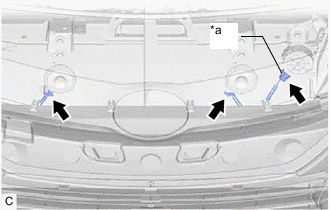
*a Vehicle Approaching Speaker Assembly Connector Disconnect the 2 horn connectors.
-
w/ Vehicle Approaching Speaker Assembly:
-
Disconnect the vehicle approaching speaker assembly connector.
-
-
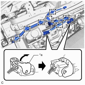
*a Lock Lever Disengage the 2 claws and raise the 2 lock levers to disconnect the cooling fan motor RH connector and cooling fan motor LH connector as shown in the illustration.
-
Disengage the 8 clamps to disconnect the wire harness from the upper radiator support sub-assembly and fan shroud.
-
for LHD:
-
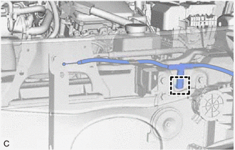
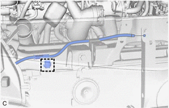
Disengage the clamp to disconnect the hood lock control cable assembly from the upper radiator support sub-assembly.
-
-
for RHD:
-
Disengage the clamp to disconnect the hood lock control cable assembly from the upper radiator support sub-assembly.
-
-
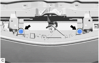
Remove the 2 bolts to separate the front bumper assembly from the upper radiator support sub-assembly.
-
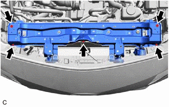
Remove the 5 bolts and upper radiator support sub-assembly.
-
-
REMOVE RADIATOR SUPPORT CUSHION
-
Remove the 2 radiator support cushions from the radiator assembly.
-
-
DISCONNECT OUTLET NO. 1 INVERTER COOLING HOSE
-
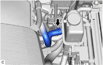
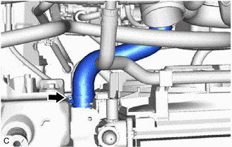
Slide the clip and disconnect the outlet No. 1 inverter cooling hose.
-
-
DISCONNECT INLET NO. 1 INVERTER COOLING HOSE
-
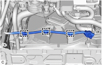
Disengage the 3 clamps to disconnect the wire harness from the fan shroud.
-
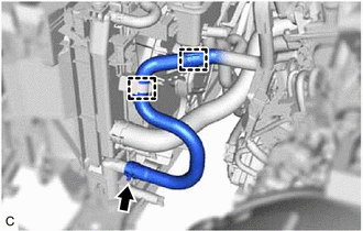
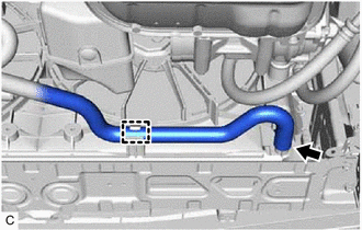
Disengage the 2 clamps to disconnect the inlet No. 1 inverter cooling hose from the fan shroud and inverter reserve tank assembly.
-
Slide the clip and disconnect the inlet No. 1 inverter cooling hose.
-
-
REMOVE INVERTER RESERVE TANK ASSEMBLY
-
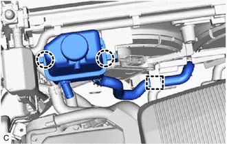
Disengage the clamp to disconnect the inlet hybrid water pump hose from the fan shroud.
-
Disengage the 2 claws to remove the inverter reserve tank assembly from the fan shroud.
-
-
DISCONNECT NO. 1 WATER BY-PASS HOSE
-
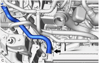
Slide the clip and disconnect the No. 1 water by-pass hose.
-
-
DISCONNECT NO. 2 WATER BY-PASS HOSE
-
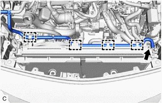
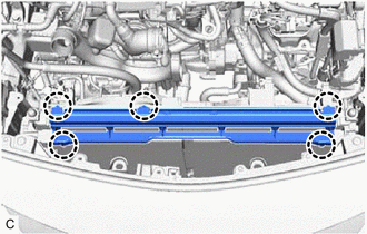
Disengage the 4 clamps to disconnect the No. 2 water by-pass hose from the fan shroud.
-
Slide the clip and disconnect the No. 2 water by-pass hose.
-
-
DISCONNECT NO. 2 RADIATOR HOSE
-
Slide the clip and disconnect the No. 2 radiator hose.
-
-
DISCONNECT INLET HYBRID RADIATOR HOSE
-
Disengage the clamp to disconnect the inlet hybrid radiator hose from the fan shroud.
-
Slide the clip and disconnect the inlet hybrid radiator hose.
-
-
REMOVE NO. 2 RADIATOR AIR GUIDE
-
Disengage the 5 claws to remove the No. 2 radiator air guide from the radiator assembly.
-
-
REMOVE FAN ASSEMBLY
-
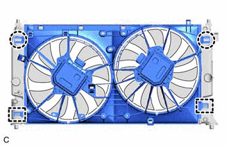
Disengage the 2 claws.
-
Disengage the 2 guides to remove the fan assembly from the radiator assembly.
Note
Do not damage the radiator assembly when removing the fan assembly.
-
-
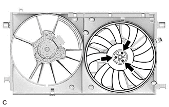
REMOVE FAN RH
-
Remove the 3 screws and fan RH.
-
-
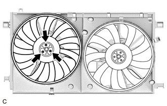
REMOVE FAN LH
-
Remove the 3 screws and fan LH.
-
-
REMOVE COOLING FAN MOTOR RH
-
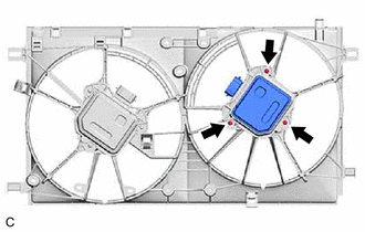
Remove the 3 screws and cooling fan motor RH.
-
-
REMOVE COOLING FAN MOTOR LH
-
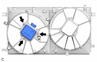
Remove the 3 screws and cooling fan motor LH.
-