FUEL TANK(w/ Canister Pump Module) INSTALLATION
PROCEDURE
-
INSTALL NO. 1 FUEL TANK PROTECTOR SUB-ASSEMBLY
-
Install the No. 1 fuel tank protector sub-assembly to the fuel tank assembly with the 3 clips.
-
-
INSTALL FUEL TANK VENT HOSE SUB-ASSEMBLY
-
Engage the 2 clamps to install the fuel tank vent hose sub-assembly to the fuel tank assembly.
-
-
INSTALL FUEL TANK MAIN TUBE SUB-ASSEMBLY
-
Engage the 3 clamps to install the fuel tank main tube sub-assembly to the fuel tank assembly.
-
-
INSTALL FUEL TANK ASSEMBLY
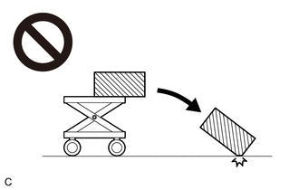
CAUTION:
The fuel tank assembly is very heavy. Be sure to follow the procedure described in the repair manual, or the fuel tank assembly may fall off the engine lifter.
-
Set the fuel tank assembly on an engine lifter.
Note
Using height adjustment attachments and plate lift attachments, keep the fuel tank assembly horizontal.
-
Using the engine lifter, slowly raise the fuel tank assembly, and then install the fuel tank assembly with the 4 bolts.
- Torque:
- 45 N*m { 459 kgf*cm, 33 ft.*lbf }
Note
-
Be careful not to drop the fuel tank assembly.
-
When installing the fuel tank assembly, tilt it slightly to prevent it from interfering with the surrounding parts.
-
-
CONNECT FUEL TANK MAIN TUBE SUB-ASSEMBLY
-
Connect the fuel tank main tube sub-assembly to the fuel pipe.
-
-
INSTALL NO. 3 PARKING BRAKE CABLE ASSEMBLY
-
Install the No. 3 parking brake cable assembly with the 2 bolts.
- Torque:
- 6.0 N*m { 61 kgf*cm, 53 in.*lbf }
-
-
CONNECT FUEL TANK TO FILLER PIPE HOSE
-
Connect the fuel tank to filler pipe hose to the fuel tank assembly.
-
-
CONNECT FUEL TANK VENT HOSE SUB-ASSEMBLY
-
Connect the fuel tank vent hose sub-assembly to the fuel tank solenoid main valve assembly.
-
-
INSTALL NO. 1 FUEL TANK PROTECTOR
-
Install the No. 1 fuel tank protector to the fuel tank assembly with the 4 clips.
-
-
INSTALL REAR FLOOR SIDE MEMBER COVER LH
-
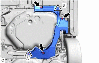
Install the rear floor side member cover LH with the clip (B).
-
Install the 3 bolts and clip (A).
- Torque:
- 7.5 N*m { 76 kgf*cm, 66 in.*lbf }
-
-
INSTALL NO. 1 FLOOR UNDER COVER ASSEMBLY
-
Install the No. 1 floor under cover assembly with the clip.
-
Install the 3 bolts.
- Torque:
- 7.5 N*m { 76 kgf*cm, 66 in.*lbf }
-
-
INSTALL TAIL EXHAUST PIPE ASSEMBLY
-
INSTALL FUEL SUCTION TUBE WITH PUMP AND GAUGE ASSEMBLY
-
ADD FUEL