FUEL SYSTEM ON-VEHICLE INSPECTION

PROCEDURE
-
CHECK FUEL PUMP WITH FILTER ASSEMBLY OPERATION AND INSPECT FOR FUEL LEAK
-
Check fuel pump with filter assembly operation.
-
Connect the GTS to the DLC3.
-
Turn the power switch on (IG) and turn the GTS on.
Note
Do not start the engine.
-
Enter the following menus: Powertrain / Engine / Active Test / Activate the Circuit Relay.
Powertrain > Engine > Active TestTester Display Activate the Circuit Relay -
Check for pressure in the fuel tube sub-assembly from the fuel line. Check that sounds of fuel flowing from the fuel tank assembly can be heard. If no sound can be heard, check the fuel pump with filter assembly, ECM and wiring connectors.
-
-
Inspect for fuel leaks.
-
Check that there are no fuel leaks from the fuel system after doing any maintenance or repairs. If there is a fuel leak, repair or replace parts as necessary.
-
-
Turn the power switch off.
-
Disconnect the GTS from the DLC3.
-
-
CHECK FUEL PRESSURE
-
Discharge the fuel system pressure.
-
Remove the front wiper motor and link assembly.
-
Remove the No. 1 heater air duct splash shield seal. (for LHD)
-
Remove the No. 2 heater air duct splash shield seal. (for RHD)
-
Remove the water guard plate.
-
Remove the cowl body mounting reinforcement LH.
-
Remove the outer cowl top panel sub-assembly.
-
Measure the auxiliary battery voltage.
Standard Voltage 11 to 14 V -
Disconnect the cable from the negative (-) auxiliary battery terminal.
Note
When disconnecting the cable, some systems need to be initialized after the cable is reconnected.
-
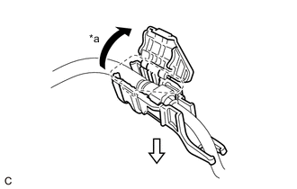
*a Open 
Pull Open the cover of the fuel pipe clamp and remove the fuel pipe clamp from the fuel tube connector.
-
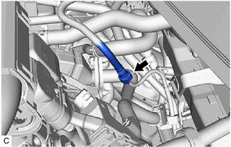
Disconnect the fuel tube sub-assembly from the fuel pipe.
-
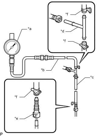
*a SST (Pressure Gauge) *b SST (Hose Joint) *c SST (Hose) *d SST (T-joint) *e SST (Fuel Tube Connector) *f SST (Hose Band) Install SST (EFI fuel pressure gauge) as shown in the illustration.
- SST
- 09268-45101 ( 09268-41260, 09268-41280, 09268-41700, 95336-08070 )
- 09268-00010 ( 09268-00020, 09268-00030 )
-
Wipe up any spilled fuel.
-
Connect the cable to the negative (-) auxiliary battery terminal.
Note
When disconnecting the cable, some systems need to be initialized after the cable is reconnected.
-
Connect the GTS to the DLC3.
-
Turn the power switch on (IG) and turn the GTS on.
Note
Do not start the engine.
-
Enter the following menus: Powertrain / Engine / Active Test / Activate the Circuit Relay.
Powertrain > Engine > Active TestTester Display Activate the Circuit Relay -
Measure the fuel pressure.
Standard Fuel Pressure 304 to 343 kPa (3.1 to 3.5 kgf/cm2, 44 to 50 psi)
-
If the fuel pressure is more than the standard, replace the fuel pressure regulator assembly.
-
If the fuel pressure is less than the standard, check the fuel hoses and their connections, fuel pump with filter assembly, fuel filter and fuel pressure regulator assembly.
-
-
Disconnect the GTS from the DLC3.
-
Put the engine in inspection mode (maintenance mode).
-
Start the engine.
-
Measure the fuel pressure at idle.
Standard Fuel Pressure 304 to 343 kPa (3.1 to 3.5 kgf/cm2, 44 to 50 psi) -
Stop the engine.
-
Check that the fuel pressure remains as specified for 5 minutes.
Standard Fuel Pressure 147 kPa (1.5 kgf/cm2, 21 psi) or more If the result is not as specified, check the fuel pump with filter assembly, fuel pressure regulator assembly and/or fuel injector assemblies.
-
After checking the fuel pressure, disconnect the cable from the negative (-) auxiliary battery terminal and carefully remove SST to prevent fuel from spraying.
Note
When disconnecting the cable, some systems need to be initialized after the cable is reconnected.
-
Connect the fuel tube sub-assembly to the fuel pipe.
-
Install the fuel pipe clamp to the fuel tube connector and close the cover of the fuel pipe clamp.
-
Inspect for fuel leaks.
-
Install the outer cowl top panel sub-assembly.
-
Install the cowl body mounting reinforcement LH.
-
Install the water guard plate.
-
Install the No. 1 heater air duct splash shield seal. (for LHD)
-
Install the No. 2 heater air duct splash shield seal. (for RHD)
-
Install the front wiper motor and link assembly.
-