HV BATTERY STACK DISCHARGING
PROCEDURE
-
DISCHARGING (WHEN USING THE LI-ION BATTERY DISCHARGER)
CAUTION:
Be sure to wear insulated gloves and protective goggles.
Note
-
Set it in a secure, flat place.
-
Set it in a dry place protected from dust and water.
-
Set it in a position where illumination of the LED indicators can be observed.
-
Do not block the ventilation holes or cooling fans.
Make sure to observe the following points when using the Li-ion battery discharger.
-
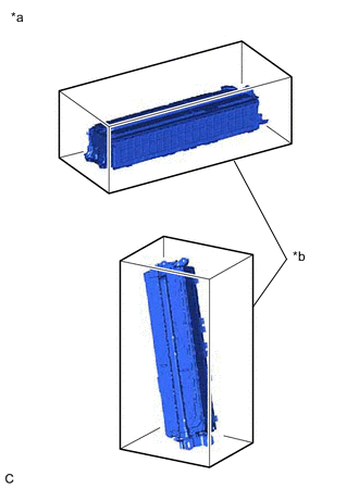
Select Li-ion battery connection cables
-
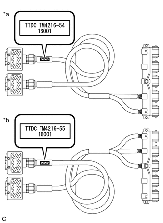
*a Li-ion Battery Connection Cable (A) *b Li-ion Battery Connection Cable (B) Confirm the type of the Li-ion battery connection cable as indicated by the tag shown in the illustration. (Type: TM4216-54.TM4216-55)
-
-
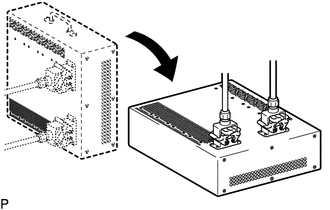
Install Li-ion battery connection cable
-
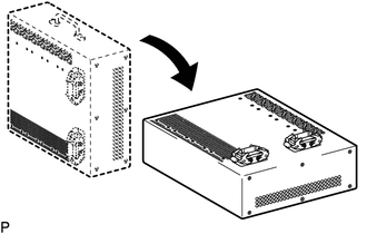
Set the Li-ion battery discharger as shown in the illustration.
-
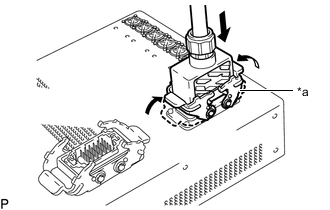
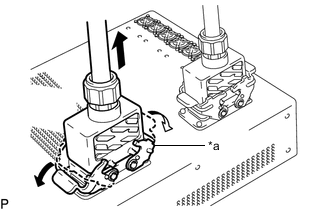
*a Connector A Connect the Li-ion battery connection cable connector (A) to the Li-ion battery discharger connector (A).
Note
Make sure that the connector is connected securely.
-
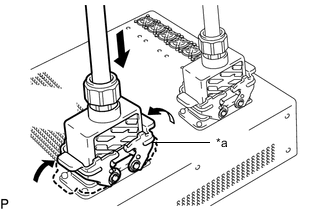
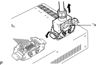
*a Connector B Connect the Li-ion battery connection cable connector (B) to the Li-ion battery discharger connector (B).
Note
Make sure that the connector is connected securely.
-
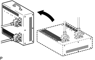
Set the Li-ion battery discharger as shown in the illustration.
Tech Tips
The Li-ion battery discharger is set on its side so that the ventilation holes will not be blocked.
-
-
Connect Li-ion battery connection cable (A)
-
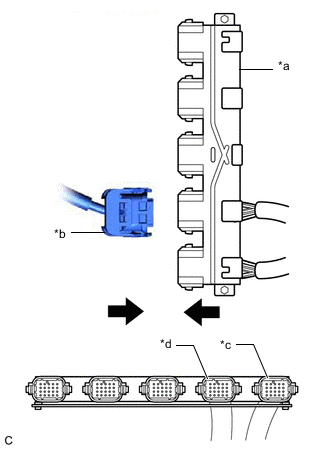
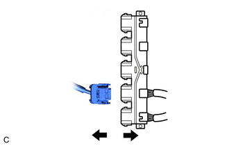
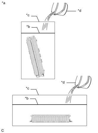
*a Li-Ion Battery Connection Cable (A) *b HV Supply Stack Sub-assembly Connector *c Connection for No. 1 HV Supply Stack Sub-assembly Connector *d Connection for No. 2 HV Supply Stack Sub-assembly Connector Connect the connector (orange) of the HV supply stack sub-assembly to be discharged to the Li-ion battery connection cable (A) (orange).
-
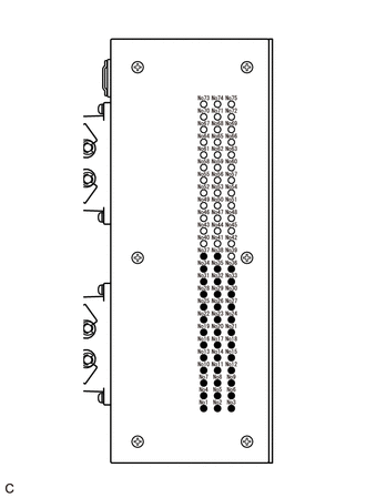
Confirm that all of the LED indicators are illuminated as shown in the following table.
CAUTION:
If all of the LED indicators of the Li-ion battery discharger listed in the following table are not illuminated, the HV supply stack sub-assembly cannot be discharged using the Li-ion battery discharger. Make sure to soak the HV supply stack sub-assembly in a salt water solution to complete discharging.
LED Indicator Illumination Status (When discharge has started normally) Item LED Indicator No. LED Indicator Illumination Status No. 1 HV supply stack sub-assembly 1 to 19 Illuminated No. 2 HV supply stack sub-assembly 20 to 38 Illuminated -
Confirm that the cooling fans operate.
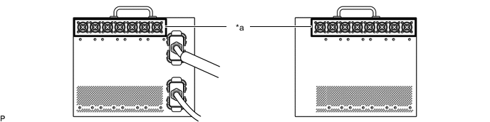
*a Cooling Fans - - Tech Tips
-
To discharge the HV supply stack sub-assembly completely, continue discharging for at least 1 hour after the LED indicators have turned off.
-
Discharge of a fully charged HV supply stack sub-assembly will complete within 25 hours (including 1 hour waiting time after the LED indicators have turned off).
-
-
-
Connect Li-ion battery connection cable (B)
-
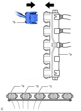
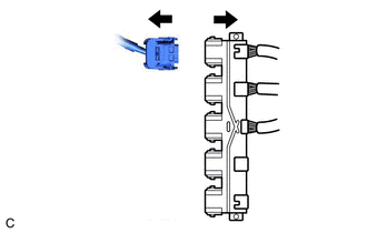
*a Li-ion Battery Connection Cable (B) *b HV Supply Stack Sub-assembly Connector *c Connection for No. 3 HV Supply Stack Sub-assembly Connector *d Connection for No. 4 HV Supply Stack Sub-assembly Connector *e Connection for No. 5 HV Supply Stack Sub-assembly Connector Connect the connector (orange) of the HV supply stack sub-assembly to be discharged to the Li-ion battery connection cable (B) (orange).
-
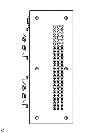
Confirm that all of the LED indicators are illuminated as shown in the following table.
CAUTION:
If all of the LED indicators of the Li-ion battery discharger listed in the following table are not illuminated, the HV supply stack sub-assembly cannot be discharged using the Li-ion battery discharger. Make sure to soak the HV supply stack sub-assembly in a salt water solution to complete discharging.
LED Indicator Illumination Status (When discharge has started normally) Item LED Indicator No. LED Indicator Illumination Status No. 3 HV supply stack sub-assembly 1 to 19 Illuminated No. 4 HV supply stack sub-assembly 20 to 38 Illuminated No. 5 HV supply stack sub-assembly 39 to 57 Illuminated -
Confirm that the cooling fans operate.
*a Cooling Fans - - Tech Tips
-
To discharge the HV supply stack sub-assembly completely, continue discharging for at least 1 hour after the LED indicators have turned off.
-
Discharge of a fully charged HV supply stack sub-assembly will complete within 25 hours (including 1 hour waiting time after the LED indicators have turned off).
-
-
-
Confirm discharge completion
-
Confirm that all of the LED indicators of the Li-ion battery discharger have turned off.
-
Continue to discharge the battery for 1 hour after all of the LED indicators of the Li-ion battery discharger have turned off.
-
-
Disconnect Li-ion battery connection cable (A)
-
Disconnect the connector (orange) of the HV supply stack sub-assembly from the Li-ion battery connection cable (orange).
-
-
Disconnect Li-ion battery connection cable (B)
-
Disconnect the connector (orange) of the HV supply stack sub-assembly from the Li-ion battery connection cable (orange).
-
-
Remove Li-ion battery connection cable
-
Set the Li-ion battery discharger as shown in the illustration.
-
*a Connector B Disconnect the Li-ion battery connection cable connector (B) from the Li-ion battery discharger connector (B).
-
*a Connector A Disconnect the Li-ion battery connection cable connector (A) from the Li-ion battery discharger connector (A).
-
-
-
DISCHARGING (WHEN USING THE SALT WATER SOLUTION)
CAUTION:
Be sure to wear insulated gloves and protective goggles.
Note
-
When discharging using salt water solution, first add a measured amount of water to the container, and then add the concentrated salt water solution.
-
Calculate the salt water concentration based on the measured volume of water in the container so that a 1% salt water solution will be made after adding the concentrated salt water solution to the water in the container where the HV supply stack sub-assembly is set.
-
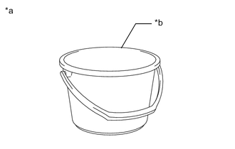
Prepare HV supply stack sub-assembly
-
*a Example *b Container A Set the HV supply stack sub-assembly in the container (A).
-
-
Prepare to discharge (Add water to container)
-
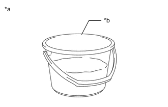
*a Example *b Container B Measure the water capacity of the container (B).
Tech Tips
Water capacity of the container (B) is assumed as X (liters).
-
*a Example *b Water Surface *c Container A *d Container B Using the container (B), add water to the container (A) until the HV supply stack sub-assembly is completely submerged.
Note
Make sure to record the times the container (B) was filled with water to add water to the container (A).
-
Using the following formula, calculate the amount of water added to the container (A).
Amount of water added to the container (A) Y (liters) = Water capacity of the container (B) x Number of times the container (B) was filled with water to submerge the HV supply stack sub-assembly Tech Tips
Amount of water added to the container (A) is assumed as Y (liters).
-
-
Prepare salt water solution
-
*a Example *b Container B While measuring the amount of water, fill about half of the container (B) with water.
Tech Tips
Amount of water added to the container (B) is assumed as Z (liters).
-
Calculate the amount of salt to be added to the container (A) so that a 1% salt water solution will be made.
Amount of Salt Amount of salt (kg) = (Y (liters) + Z (liters)) x 0.01 -
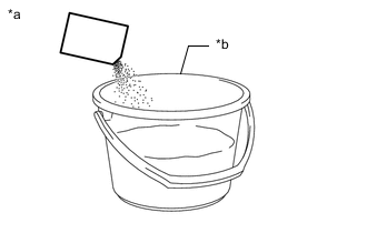
*a Example *b Container B Add the calculated amount of salt to the container (B) and stir it thoroughly.
-
-
Add salt water solution
-
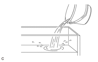
Add the concentrated salt water solution to the container (A).
-
-
Discharge
-
Leave the HV supply stack sub-assembly as is for 24 hours or more until discharge is complete.
CAUTION:
-
Do not place a lid on the container.
-
Make sure to leave the HV supply stack sub-assembly and container as is for 24 hours or more.
-
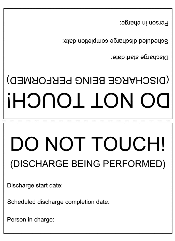
Display a warning sign to inform others that discharge is being performed.
-
-
-
Confirm discharge completion
-
Check that bubbles are not forming in the container.
Note
If bubbles are forming, discharge may not be completed yet. Do not place a lid on the container.
-
-
Display a warning sign such as "DO NOT TOUCH! (DISCHARGE BEING PERFORMED) to inform others. Make a copy of the warning sign and place it near the HV supply stack sub-assembly being discharged.
-