HV BATTERY STACK RECOVERY INSPECTION
| DTC Code | DTC Name |
|---|---|
| RECOVERY INSPECTION |
CAUTION / NOTICE / HINT
CAUTION:
-
When disposing of an HV supply stack sub-assembly, make sure to return it through an authorized collection agent who is capable of handling it safely. If it is returned via the manufacturer specified route, it will be returned properly and in a safe manner by an authorized collection agent.
-
Before returning an HV supply stack sub-assembly, make sure to perform a pre-return inspection.
-
Accidents such as electric shock may result if an HV supply stack sub-assembly is discharged improperly and disposed or abandoned.
Therefore, make sure to return all HV supply stack sub-assemblies through an authorized collection agent.
-
To reduce the risk of fire, HV supply stack sub-assemblies must not be stored in an area where they will be exposed to fire or high temperatures.
-
If the temperature of an HV supply stack sub-assembly is high, leave it to cool down.
Tech Tips
In order to return an HV supply stack sub-assembly in a safe manner, it may be necessary to discharge it. The following pre-return inspection procedure can be used to determine whether or not it is necessary to discharge an HV supply stack sub-assembly the method that may be required.
PROCEDURE
-
INSPECT FOR ELECTROLYTE LEAK
CAUTION:
Be sure to wear insulated gloves and protective goggles.
-
Inspect for electrolyte leaks after removing the HV supply stack sub-assembly.
OK No leak was found on the lower part of the battery outer case. CAUTION:
-
Perform this procedure in an area where the battery will not be exposed to fire.
-
Do not touch the HV supply stack sub-assembly, unless absolutely necessary, as electrolyte may be leaking.
Note
If there is an electrolyte leak, make sure to wear insulated gloves and goggles and clean it using a piece of cloth. Do not leave electrolyte-contaminated cloths unattended. Dispose of them according to law or local regulations.
Result Result OK NG -
NG 
DISCHARGING (WHEN USING THE SALT WATER SOLUTION)
OK 
-
-
CHECK FOR DTCS
-
Check the previously recorded DTCs which resulted in replacement of the HV supply stack sub-assembly.
Result Result Proceed to DTC record not available. A The HV supply stack sub-assembly was replaced due to one of the DTCs listed in the following table. B The HV supply stack sub-assembly was replaced due to a reason other than the DTCs listed in the following table. C DTC No. P1A6017 P1A6317 P1A6617 P1A6917 P31AA17 P0C3000 P31B300 P1C7D49
B 
GO TO STEP 5 Click here
C
HV SUPPLY STACK SUB-ASSEMBLY CONNECTORS VISUAL CHECK Click here
A
-
-
CHECK HV SUPPLY STACK SUB-ASSEMBLY VOLTAGE
CAUTION:
Be sure to wear insulated gloves and protective goggles.
-
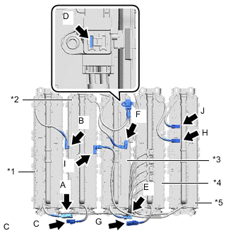
*1 No. 1 HV Supply Stack Sub-assembly *2 No. 2 HV Supply Stack Sub-assembly *3 No. 3 HV Supply Stack Sub-assembly *4 No. 4 HV Supply Stack Sub-assembly *5 No. 5 HV Supply Stack Sub-assembly Measure the voltage according to the value(s) in the table below.
Standard Voltage Tester Connection Condition Specified Condition A - B Always Below 70.3 V C - D E - F G - H I - J CAUTION:
Make sure not to cross the probes of the electrical tester.
Result Result OK NG
NG
GO TO STEP 6 Click here
OK
-
-
INSULATION INSPECTION OF HV SUPPLY STACK SUB-ASSEMBLY
CAUTION:
Be sure to wear insulated gloves and protective goggles.
-
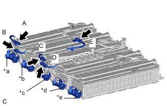
*a Insulation Inspection Area of the Bracket A *b Insulation Inspection Area of the Bracket B *c Insulation Inspection Area of the Bracket C *d Insulation Inspection Area of the Bracket D *e Insulation Inspection Area of the Bracket E Using a megohmmeter set to 500 V, measure the insulation resistance according to the value(s) in the table below.
Note
Be sure to set the megohmmeter to 500 V when performing this test. Using a setting higher than 500 V can result in damage to the component being inspected.
Standard Resistance Tester Connection Condition Specified Condition A - Insulation Inspection Area of the Bracket A Always 1 MΩ or higher B - Insulation Inspection Area of the Bracket B C - Insulation Inspection Area of the Bracket C D - Insulation Inspection Area of the Bracket D E - Insulation Inspection Area of the Bracket E Result Result OK NG
NG
GO TO STEP 6 Click here
OK
-
-
HV SUPPLY STACK SUB-ASSEMBLY VISUAL CHECK
CAUTION:
Be sure to wear insulated gloves and protective goggles.
-
Check that the HV supply stack sub-assembly is not deformed or damaged.
OK The HV supply stack sub-assembly is not deformed or damaged. Result Result OK NG
OK
RETURN HV SUPPLY STACK SUB-ASSEMBLY
NG
-
-
HV SUPPLY STACK SUB-ASSEMBLY CONNECTORS VISUAL CHECK
CAUTION:
Be sure to wear insulated gloves and protective goggles.
-
Check that the orange connectors connected to the battery ECU assembly are not deformed or damaged.
OK The connectors are not deformed or damaged. Tech Tips
If any of the connectors are damaged, a Li-ion battery discharger will not be able to be connected to the HV supply stack sub-assembly. Soak the HV supply stack sub-assembly in a salt water solution to discharge it.
Result Result OK NG
OK
DISCHARGING (WHEN USING THE LI-ION BATTERY DISCHARGER)
NG
DISCHARGING (WHEN USING THE SALT WATER SOLUTION)
-