HV BATTERY STACK REMOVAL
CAUTION / NOTICE / HINT
The necessary procedures (adjustment, calibration, initialization, or registration) that must be performed after parts are removed and installed, or replaced during HV supply stack sub-assembly removal/installation are shown below.
| Replaced Part or Performed Procedure | Necessary Procedures | Effect/Inoperative Function when Necessary Procedure not Performed | Link |
|---|---|---|---|
| Auxiliary battery terminal is disconnected/reconnected | Memorize steering angle neutral point | Lane departure alert system (w/ Steering Control) | |
| Intelligent clearance sonar system*1 | |||
| Simple intelligent parking assist system*1 | |||
| Pre-crash safety system | |||
| Adaptive high beam system | |||
| Parking assist monitor system | |||
| Initialize back door lock | Power door lock control system | ||
|
|
HV battery status information cannot be updated | |
|
Current sensor offset learning | DTCs are stored | |
| Replacement of hybrid battery terminal block | Perform high voltage fuse accumulated load history reset |
Click here Click here
CAUTION:
-
Orange wire harnesses and connectors indicate high-voltage circuits. To prevent electric shock, always follow the procedure described in the repair manual.
-

To prevent electric shock, wear insulated gloves when working on wire harnesses and components of the high voltage system.
-
The hybrid system has high-voltage circuits. Accidents, such as electric shock, or electric leaks may result if the hybrid system is not operated in a correct manner. Make sure to follow the correct procedure.
-
When disposing of an HV battery or HV supply stack sub-assembly, make sure to return them through an authorized collection agent who is capable of handling them safely.
-
Before returning an HV battery, make sure to perform a recovery inspection.
-
Before returning an HV supply stack sub-assembly, make sure to perform a recovery inspection.
-
Make a note of the output DTCs as some of them may be necessary for "Recovery Inspection" of the HV battery and HV supply stack sub-assemblies.
Note
When replacing the HV supply stack sub-assembly, it is necessary to check, adjust and equalize the SOC of the HV battery. Otherwise, the engine may run longer than normal, resulting in a decrease in fuel efficiency.
PROCEDURE
-
PRECAUTION
Note
After turning the power switch off, waiting time may be required before disconnecting the cable from the negative (-) auxiliary battery terminal. Therefore, make sure to read the disconnecting the cable from the negative (-) auxiliary battery terminal notices before proceeding with work.
-
READ VALUE USING GTS
-
Connect the GTS to the DLC3.
-
Turn the power switch on (IG).
-
Enter the following menus: Powertrain / HV Battery / Data List / Hybrid Battery Temperature 1 to 15.
Powertrain > HV Battery > Data ListTester Display Hybrid Battery Temperature 1 Hybrid Battery Temperature 2 Hybrid Battery Temperature 3 Hybrid Battery Temperature 4 Hybrid Battery Temperature 5 Hybrid Battery Temperature 6 Hybrid Battery Temperature 7 Hybrid Battery Temperature 8 Hybrid Battery Temperature 9 Hybrid Battery Temperature 10 Hybrid Battery Temperature 11 Hybrid Battery Temperature 12 Hybrid Battery Temperature 13 Hybrid Battery Temperature 14 Hybrid Battery Temperature 15 -
Read the Data List.
Note
If any of the temperatures listed in "Hybrid Battery Temperature 1 to 15" are 50°C or more, leave the vehicle until the temperature drops to less than 50°C.
-
-
REMOVE HV BATTERY JUNCTION BLOCK ASSEMBLY
-
REMOVE BATTERY ECU ASSEMBLY
-
REMOVE HYBRID BATTERY TERMINAL BLOCK
-
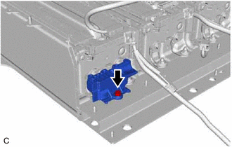
REMOVE HV BATTERY HEATER RELAY
-
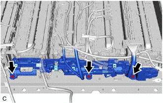
DISCONNECT WIRE HARNESS
CAUTION:
Be sure to wear insulated gloves and protective goggles.
-
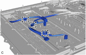
Disengage the 3 clamps.
-
Disconnect the connector.
-
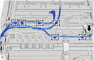
Disengage the 6 clamps.
-
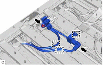
Disconnect the connector.
-
Disengage the 3 clamps.
-
Remove the nut.
-
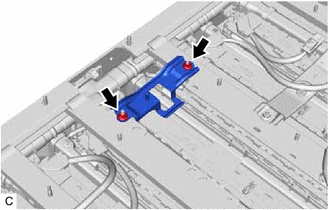
Remove the 2 nuts and service plug bracket.
-
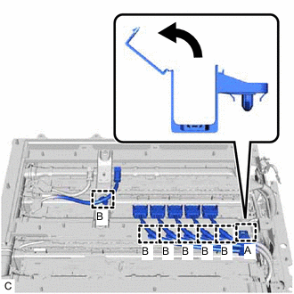
Open the wire harness protector.
-
Disengage the 6 clamps (B).
-
Disengage the clamp (A) and remove the wire harness protector.
-
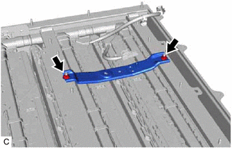
Remove the 2 nuts and fuse box bracket.
-
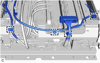
Disengage the 4 clamps.
-
-
REMOVE NO. 1 BATTERY FRAME
CAUTION:
Be sure to wear insulated gloves and protective goggles.
-
Remove the 3 nuts and No. 1 battery frame.
-
-
REMOVE NO. 2 BATTERY FRAME
CAUTION:
Be sure to wear insulated gloves and protective goggles.
-
Remove the 2 nuts and No. 2 battery frame.
-
-
REMOVE NO. 1 HYBRID BATTERY EXHAUST DUCT
CAUTION:
Be sure to wear insulated gloves and protective goggles.
-
Disengage the 2 claws to remove the No. 1 hybrid battery exhaust duct from the HV battery.
-
-
REMOVE NO. 4 HYBRID BATTERY INTAKE DUCT
CAUTION:
Be sure to wear insulated gloves and protective goggles.
-
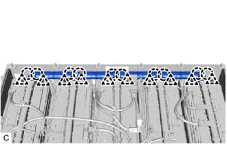
Remove the 5 clips and 5 No. 4 hybrid battery intake ducts from the HV battery.
-
-
REMOVE NO. 1 HV BATTERY HOSE
CAUTION:
Be sure to wear insulated gloves and protective goggles.
-
Remove the 10 clips.
-
Disengage 10 claws to remove the No. 1 HV battery hose.
-
-
REMOVE NO. 1 HYBRID BATTERY PACK WIRE
CAUTION:
Be sure to wear insulated gloves and protective goggles.
Note
Insulate each disconnected high-voltage connector with insulating tape. Wrap the connector from the wire harness side to the end of the connector.
-
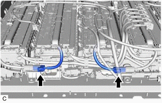
Disconnect the 2 connectors.
-
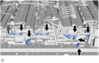
Disconnect the 7 connectors.
-
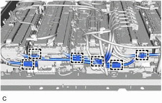
Disengage the 6 clamps.
-
Remove the 3 bolts and No. 1 hybrid battery pack wire from the HV battery.
-
-
REMOVE NO. 1 HV BATTERY PROTECTOR
CAUTION:
Be sure to wear insulated gloves and protective goggles.
-
Remove the bolt and No. 1 HV battery protector from the HV battery.
-
-
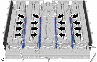
REMOVE NO. 7 HYBRID BATTERY INTAKE DUCT
CAUTION:
Be sure to wear insulated gloves and protective goggles.
-
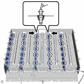
Disengage the 2 claws of 2 hybrid battery thermistors (sensor portion) and disconnect the hybrid battery thermistor from the No. 7 hybrid battery intake duct.
-
Disengage each claw to remove the 5 No. 7 hybrid battery intake ducts.
-
-
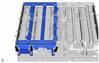
REMOVE NO. 1 HV BATTERY SHIELD REINFORCEMENT
CAUTION:
Be sure to wear insulated gloves and protective goggles.
-
Remove the 16 bolts and 4 No. 1 HV battery shield reinforcements.
-
-
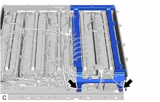
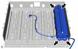
REMOVE NO. 1 HV SUPPLY STACK SUB-ASSEMBLY
CAUTION:
Be sure to wear insulated gloves and protective goggles.
-
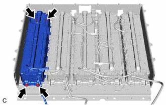
Remove the 4 nuts and No. 1 HV supply stack sub-assembly.
-
-
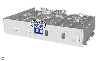
REMOVE NO. 2 HV SUPPLY STACK SUB-ASSEMBLY
CAUTION:
Be sure to wear insulated gloves and protective goggles.
-
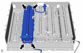
Remove the 4 nuts and No. 2 HV supply stack sub-assembly.
-
-
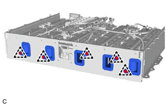
REMOVE NO. 3 HV SUPPLY STACK SUB-ASSEMBLY
CAUTION:
Be sure to wear insulated gloves and protective goggles.
-
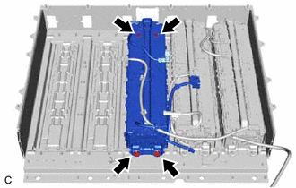
Remove the 4 nuts and No. 3 HV supply stack sub-assembly.
-
-
REMOVE NO. 4 HV SUPPLY STACK SUB-ASSEMBLY
CAUTION:
Be sure to wear insulated gloves and protective goggles.
-
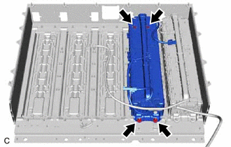
Remove the 4 nuts and No. 4 HV supply stack sub-assembly.
-
-
REMOVE NO. 5 HV SUPPLY STACK SUB-ASSEMBLY
CAUTION:
Be sure to wear insulated gloves and protective goggles.
-
Remove the 4 nuts and No. 5 HV supply stack sub-assembly.
-
-
PERFORM RECOVERY INSPECTION
-
Before returning the HV supply stack sub-assembly, make sure to perform a recovery inspection.
-