HV BATTERY HEATER REMOVAL
CAUTION / NOTICE / HINT
The necessary procedures (adjustment, calibration, initialization, or registration) that must be performed after parts are removed and installed, or replaced during HV battery heater sub-assembly removal/installation are shown below.
| Replaced Part or Performed Procedure | Necessary Procedures | Effect/Inoperative Function when Necessary Procedure not Performed | Link |
|---|---|---|---|
| Auxiliary battery terminal is disconnected/reconnected | Memorize steering angle neutral point | Lane departure alert system (w/ Steering Control) | |
| Intelligent clearance sonar system*1 | |||
| Simple intelligent parking assist system*1 | |||
| Pre-crash safety system | |||
| Adaptive high beam system | |||
| Parking assist monitor system | |||
| Initialize back door lock | Power door lock control system | ||
|
|
HV battery status information cannot be updated | |
|
Current sensor offset learning | DTCs are stored | |
| Replacement of hybrid battery terminal block | Perform high voltage fuse accumulated load history reset |
Click here Click here
CAUTION:
-
Orange wire harnesses and connectors indicate high-voltage circuits. To prevent electric shock, always follow the procedure described in the repair manual.
-

To prevent electric shock, wear insulated gloves when working on wire harnesses and components of the high voltage system.
-
The hybrid system has high-voltage circuits. Accidents, such as electric shock, or electric leaks may result if the hybrid system is not operated in a correct manner. Make sure to follow the correct procedure.
PROCEDURE
-
PRECAUTION
Note
After turning the power switch off, waiting time may be required before disconnecting the cable from the negative (-) auxiliary battery terminal. Therefore, make sure to read the disconnecting the cable from the negative (-) auxiliary battery terminal notices before proceeding with work.
-
REMOVE HV BATTERY JUNCTION BLOCK ASSEMBLY
-
REMOVE BATTERY ECU ASSEMBLY
-
REMOVE HYBRID BATTERY TERMINAL BLOCK
-
REMOVE HV BATTERY HEATER RELAY
CAUTION:
Be sure to wear insulated gloves and protective goggles.
-
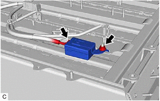
Disconnect the HV battery heater relay connector.
-
Remove the nut and HV battery heater relay from the HV battery.
-
-
DISCONNECT WIRE HARNESS
-
REMOVE NO. 1 BATTERY FRAME
-
REMOVE NO. 2 BATTERY FRAME
-
REMOVE NO. 1 HYBRID BATTERY EXHAUST DUCT
-
REMOVE NO. 4 HYBRID BATTERY INTAKE DUCT
-
REMOVE NO. 1 HV BATTERY HOSE
-
REMOVE NO. 1 HYBRID BATTERY PACK WIRE
-
REMOVE NO. 1 HV BATTERY PROTECTOR
-
REMOVE NO. 7 HYBRID BATTERY INTAKE DUCT
-
REMOVE NO. 1 HV BATTERY SHIELD REINFORCEMENT
-
REMOVE NO. 1 HV SUPPLY STACK SUB-ASSEMBLY
-
REMOVE NO. 2 HV SUPPLY STACK SUB-ASSEMBLY
-
REMOVE NO. 3 HV SUPPLY STACK SUB-ASSEMBLY
-
REMOVE NO. 4 HV SUPPLY STACK SUB-ASSEMBLY
-
REMOVE NO. 5 HV SUPPLY STACK SUB-ASSEMBLY
-
REMOVE HV BATTERY HEATER SUB-ASSEMBLY
CAUTION:
Be sure to wear insulated gloves and protective goggles.
-
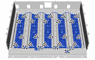
Remove the 20 clips.
-
Disengage the 5 clamps to remove the HV battery heater sub-assembly.
-