SERVICE PLUG GRIP REMOVAL
CAUTION / NOTICE / HINT
The necessary procedures (adjustment, calibration, initialization, or registration) that must be performed after parts are removed and installed, or replaced during service plug grip removal/installation are shown below.
| Replaced Part or Performed Procedure | Necessary Procedures | Effect/Inoperative Function when Necessary Procedure not Performed | Link |
|---|---|---|---|
| Auxiliary battery terminal is disconnected/reconnected | Memorize steering angle neutral point | Lane departure alert system (w/ Steering Control) | |
| Intelligent clearance sonar system*1 | |||
| Simple intelligent parking assist system*1 | |||
| Pre-crash safety system | |||
| Adaptive high beam system | |||
| Parking assist monitor system | |||
| Initialize back door lock | Power door lock control system |
Click here Click here
CAUTION:
-
Orange wire harnesses and connectors indicate high-voltage circuits. To prevent electric shock, always follow the procedure described in the repair manual.
-

To prevent electric shock, wear insulated gloves when working on wire harnesses and components of the high voltage system.
PROCEDURE
-
PRECAUTION
Note
After turning the power switch off, waiting time may be required before disconnecting the cable from the negative (-) auxiliary battery terminal. Therefore, make sure to read the disconnecting the cable from the negative (-) auxiliary battery terminal notices before proceeding with work.
-
CHECK FOR DTC
-
Check for DTCs.
CAUTION:
-
Confirm that DTC P0AA649 (Hybrid / EV Battery Voltage System Isolation Internal Electronic Failure), P1C7C49 (Hybrid / EV Battery Voltage System Isolation (A/C Area) Internal Electronic Failure), P1C7D49 (Hybrid / EV Battery Voltage System Isolation (Hybrid/EV Battery Area) Internal Electronic Failure), P1C7E49 (Hybrid / EV Battery Voltage System Isolation (Transaxle Area) Internal Electronic Failure) or P1C7F49 (Hybrid / EV Battery Voltage System Isolation (Direct Current Area) Internal Electronic Failure), P1CF749 (Hybrid/EV Battery Voltage System Isolation (Charger Area) Internal Electronic Failure), P33CF49 (Hybrid/EV Battery Voltage System Isolation Internal Electronic Failure Abnormal Area Detection Failure) is not output before removing or installing the HV battery. If this DTC is output, perform troubleshooting for this DTC first.
-
To reduce the risk of electric shock, do not perform troubleshooting before checking for DTCs.
-
-
-
DISCONNECT CABLE FROM NEGATIVE AUXILIARY BATTERY TERMINAL
Note
When disconnecting the cable, some systems need to be initialized after the cable is reconnected.
-
REMOVE REAR NO. 2 FLOOR BOARD
-
REMOVE REAR NO. 1 FLOOR BOARD
-
REMOVE NO. 4 HV BATTERY SHIELD PANEL
-
Remove the 4 nuts and No. 4 HV battery shield panel from the HV battery.
-
-
REMOVE SERVICE PLUG GRIP
CAUTION:
-
Wear insulated gloves.
-

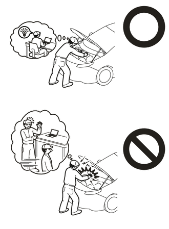
Do not inspect or service the high voltage system with the service plug grip installed.
-
To reduce the risk of electric shock, make sure to remove the service plug grip to cut off the high voltage circuit before servicing the vehicle.
-
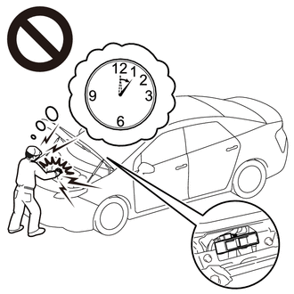
To reduce the risk of electric shock, make sure to wait at least 10 minutes after removing the service plug grip to fully discharge the high voltage capacitor inside the inverter with converter assembly.
-
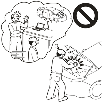
Keep the removed service plug grip in your pocket to prevent other technicians from accidentally installing it while you are servicing the vehicle.
Note
-
After removing the service plug grip, turning the power switch on (READY) may cause a malfunction. Do not turn the power switch on (READY) unless instructed by the repair manual.
-
Do not touch the terminals of the service plug grip.
-
If the service plug grip has been struck or dropped, replace it.
Tech Tips
Waiting for at least 10 minutes is required to discharge the high voltage capacitor inside the inverter with converter assembly.
-
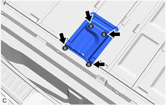
While wearing insulated gloves, rotate the handle of the service plug grip and remove the service plug grip as indicated by the arrows, in the order shown in the illustration.
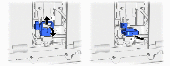
-