ENGINE ASSEMBLY INSTALLATION
CAUTION / NOTICE / HINT
CAUTION:
-
The engine assembly with transaxle is very heavy. Be sure to follow the procedure described in the repair manual, or the engine lifter may suddenly drop or the engine assembly with transaxle may fall off the engine lifter.
-
To prevent burns, do not touch the engine, exhaust manifold or other high temperature components while the engine is hot.
PROCEDURE
-
INSTALL ENGINE HANGERS
-
REMOVE ENGINE ASSEMBLY FROM ENGINE STAND
-
Remove the engine assembly from the engine stand.
-
-
INSTALL ONE-WAY CLUTCH HOLDING PLATE
-
INSTALL ONE-WAY CLUTCH ASSEMBLY
-
INSTALL FLYWHEEL SUB-ASSEMBLY
-
INSTALL TRANSMISSION INPUT DAMPER ASSEMBLY
-
INSTALL ENGINE ASSEMBLY
-
INSTALL ENGINE WIRE
-
Install the engine wire to the engine assembly with transaxle.
-
-
INSTALL STARTER HOLE INSULATOR
-
INSTALL ENGINE MOUNTING INSULATOR SUB-ASSEMBLY RH
Tech Tips
Perform this procedure only when replacement of the engine mounting insulator sub-assembly RH is necessary.
-
*a Bolt *b Nut Install the engine mounting insulator sub-assembly RH with the 2 bolts and nut.
- Torque:
- 72 N*m { 734 kgf*cm, 53 ft.*lbf }
Note
Temporarily tighten the bolt (A), and then fully tighten the 2 bolts and nut in the order of (B), (A) and (C).
-
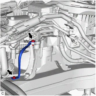
Install the No. 2 earth wire to the engine mounting insulator sub-assembly RH and vehicle body with the 2 bolts.
- Torque:
- 10.5 N*m { 107 kgf*cm, 8 ft.*lbf }
-
-
INSTALL ENGINE MOUNTING INSULATOR LH
Tech Tips
Perform this procedure only when replacement of the engine mounting insulator LH is necessary.
-
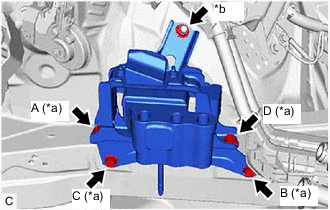
*a Bolt *b Nut Install the engine mounting insulator LH with the 4 bolts and nut.
- Torque:
- 42 N*m { 428 kgf*cm, 31 ft.*lbf }
Note
Temporarily tighten the bolt (A), and then fully tighten the 4 bolts and nut in the order of (B), (C), (D), (A) and (E).
-
-
INSTALL ENGINE ASSEMBLY WITH TRANSAXLE
-
Using height adjustment attachments and plate lift attachments to keep the engine assembly with transaxle and front suspension crossmember sub-assembly level, set an engine lifter underneath the engine assembly with transaxle and front suspension crossmember sub-assembly.
Note
-
Do not perform any procedures while the engine assembly is suspended because doing so may cause the engine assembly to drop, resulting in injury. However, the engine assembly needs to be suspended when it is installed to or removed from an engine stand.
-
To prevent the engine assembly from unexpectedly moving, securely support the engine assembly until it is secured to an engine stand.
-
-
Remove the 2 bolts, No. 1 engine hanger and No. 2 engine hanger.
-
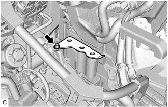
Install the wiring harness clamp bracket to the cylinder head sub-assembly with the bolt.
- Torque:
- 39 N*m { 398 kgf*cm, 29 ft.*lbf }
-
Engage the 3 clamps.
-
Operate the engine lifter and install the engine assembly with transaxle to the vehicle.
CAUTION:
Do not raise the engine assembly with transaxle more than necessary. If the engine is raised excessively, the vehicle may also be lifted up.
Note
-
Make sure that the engine assembly with transaxle is clear of all wiring and hoses.
-
While raising the engine assembly with transaxle into the vehicle, do not allow it to contact the vehicle.
-
-
Connect the front suspension crossmember sub-assembly to the vehicle with the 4 bolts.
- Torque:
- 141 N*m { 1438 kgf*cm, 104 ft.*lbf }
-
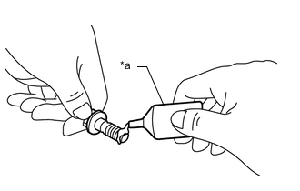
*a Adhesive Apply adhesive to 2 or 3 threads at the end of each of the bolt.
Adhesive Toyota Genuine Adhesive 1324, Three Bond 1324 or equivalent -
Install the No. 2 engine mounting stay LH with the bolt.
- Torque:
- 8.0 N*m { 82 kgf*cm, 71 in.*lbf }
-
*a Bolt *b Nut Connect the engine mounting insulator LH to the hybrid vehicle transaxle assembly with the 3 bolts and nut.
- Torque:
- Bolt
- 70 N*m { 714 kgf*cm, 52 ft.*lbf }
- Nut
- 20 N*m { 204 kgf*cm, 15 ft.*lbf }
-
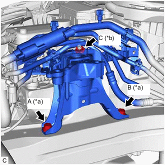
Connect the engine mounting insulator sub-assembly RH to the engine mounting bracket RH with the 2 bolts.
- Torque:
- 72 N*m { 734 kgf*cm, 53 ft.*lbf }
-
Install the nut.
- Torque:
- 41 N*m { 418 kgf*cm, 30 ft.*lbf }
-
Connect the 2 cooler brackets to the engine mounting insulator sub-assembly RH with the bolt and nut.
- Torque:
- 9.8 N*m { 100 kgf*cm, 87 in.*lbf }
-
-
INSTALL REAR SIDE RAIL REINFORCEMENT SUB-ASSEMBLY LH
-
INSTALL REAR SIDE RAIL REINFORCEMENT SUB-ASSEMBLY RH
Tech Tips
Use the same procedure as for the LH side.
-
INSTALL FRONT DRIVE SHAFT HOLE SNAP RING
-
INSTALL FRONT DRIVE SHAFT ASSEMBLY LH
-
INSTALL FRONT DRIVE SHAFT ASSEMBLY RH
Tech Tips
Use the same procedure as for the LH side.
-
CONNECT FRONT LOWER NO. 1 SUSPENSION ARM SUB-ASSEMBLY LH
-
CONNECT FRONT LOWER NO. 1 SUSPENSION ARM SUB-ASSEMBLY RH
Tech Tips
Use the same procedure as for the LH side.
-
INSTALL FRONT STABILIZER LINK ASSEMBLY LH
-
INSTALL FRONT STABILIZER LINK ASSEMBLY RH
Tech Tips
Use the same procedure as for the LH side.
-
CONNECT TIE ROD END SUB-ASSEMBLY LH
-
CONNECT TIE ROD END SUB-ASSEMBLY RH
Tech Tips
Use the same procedure as for the LH side.
-
INSTALL FRONT SPEED SENSOR LH
-
INSTALL FRONT SPEED SENSOR RH
Tech Tips
Use the same procedure as for the LH side.
-
INSTALL FRONT AXLE SHAFT NUT LH
-
INSTALL FRONT AXLE SHAFT NUT RH
Tech Tips
Use the same procedure as for the LH side.
-
CONNECT OUTLET NO. 1 OIL COOLER HOSE
-
Connect the outlet No. 1 oil cooler hose to the hybrid vehicle transaxle assembly and slide the clip to secure it.
-
-
CONNECT INLET NO. 1 OIL COOLER HOSE
-
Connect the inlet No. 1 oil cooler hose to the hybrid vehicle transaxle assembly and slide the clip to secure it.
-
-
INSTALL FRONT EXHAUST PIPE ASSEMBLY (TWC: Rear Catalyst)
-
INSTALL FRONT CENTER FLOOR BRACE
-
INSTALL FRONT FLOOR COVER LH
-
INSTALL FRONT FLOOR COVER RH
Tech Tips
Use the same procedure as for the LH side.
-
CONNECT NO. 1 STEERING COLUMN HOLE COVER SUB-ASSEMBLY
-
CONNECT NO. 2 STEERING INTERMEDIATE SHAFT ASSEMBLY
-
INSTALL COLUMN HOLE COVER SILENCER SHEET
-
CONNECT NO. 3 ENGINE WIRE
-
Connect the No. 3 engine wire to hybrid vehicle transaxle assembly with the bolt.
- Torque:
- 12.5 N*m { 127 kgf*cm, 9 ft.*lbf }
-
Engage the clamp.
-
-
INSTALL COMPRESSOR WITH MOTOR ASSEMBLY
-
Type A:
-
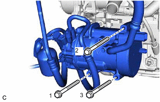
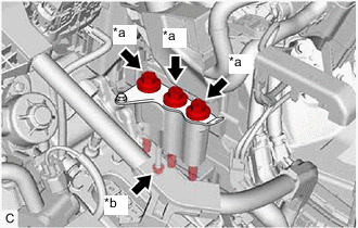
Install the compressor with motor assembly with the 3 bolts.
- Torque:
- 25 N*m { 255 kgf*cm, 18 ft.*lbf }
Tech Tips
Tighten the 3 bolts in the order shown in the illustration.
-
-
Type B:
-
Using an E8 "TORX" socket wrench, temporarily install the compressor with motor assembly with the 2 stud bolts.
- Torque:
- 9.8 N*m { 100 kgf*cm, 87 in.*lbf }
-
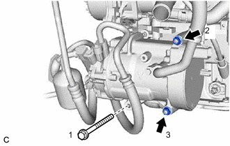
Install the compressor with motor assembly with the bolt and 2 nuts.
- Torque:
- 25 N*m { 255 kgf*cm, 18 ft.*lbf }
Tech Tips
Tighten the bolt and nuts in the order shown in the illustration.
-
-
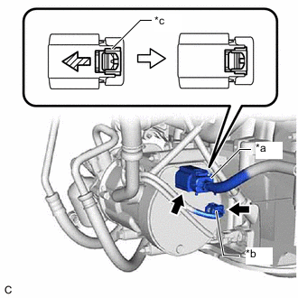
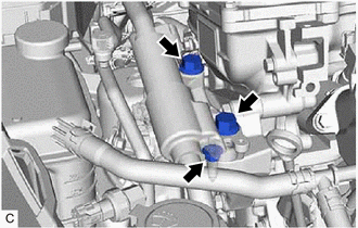
*a Connector (A) *b Connector (B) *c Green-colored Lock Connect connector (B).
-
Connect connector (A) and slide the green-colored lock as shown in the illustration to lock it securely.
CAUTION:
Make sure to wear insulating gloves.
Note
Make sure that the connector is connected securely.
-
Connect the bracket with the bolt.
- Torque:
- 8.0 N*m { 82 kgf*cm, 71 in.*lbf }
-
-
CONNECT OUTLET NO. 1 HYBRID WATER PUMP HOSE
-
Connect the outlet No. 1 hybrid water pump hose to the motor cooling cooler and slide the clip to secure it.
-
-
CONNECT INLET HYBRID RADIATOR HOSE
-
Connect the inlet hybrid radiator hose to the motor cooling cooler and slide the clip to secure it.
-
-
CONNECT FUEL TUBE SUB-ASSEMBLY
-
CONNECT NO. 1 FUEL VAPOR FEED HOSE
-
Connect the No. 1 fuel vapor feed hose to the fuel vapor feed pipe and slide the clip to secure it.
-
-
CONNECT INLET HEATER WATER HOSE A
-
Connect the inlet heater water hose A to the EGR valve assembly and slide the clip to secure it.
-
-
CONNECT OUTLET HEATER WATER HOSE E
-
Connect the outlet heater water hose E to the No. 1 water by-pass pipe and slide the clip to secure it.
-
-
CONNECT NO. 2 RADIATOR HOSE
-
Connect the No. 2 radiator hose to the water inlet sub-assembly and slide the clip to secure it.
-
-
CONNECT NO. 3 RADIATOR HOSE
-
Connect the No. 3 radiator hose to the water outlet and slide the clip to secure it.
-
Install the 2 bolts to the hybrid vehicle transaxle assembly.
- Torque:
- 19 N*m { 194 kgf*cm, 14 ft.*lbf }
-
-
INSTALL INVERTER WITH CONVERTER ASSEMBLY
-
INSTALL INLET NO. 1 AIR CLEANER
-
INSTALL AIR CLEANER BRACKET
-
INSTALL AIR CLEANER CASE SUB-ASSEMBLY
-
INSTALL AIR CLEANER FILTER ELEMENT SUB-ASSEMBLY
-
INSTALL THROTTLE BODY ASSEMBLY
-
INSTALL INLET NO. 2 AIR CLEANER
-
INSTALL RADIATOR SUPPORT OPENING COVER
-
CONNECT NO. 8 WATER BY-PASS HOSE
-
Connect the No. 8 water by-pass hose to the No. 2 water by-pass hose assembly and slide the clip to secure it.
-
-
ADD ENGINE OIL
-
ADD HYBRID TRANSAXLE FLUID
-
ADD ENGINE COOLANT (for Engine)
-
CHECK ENGINE OIL LEVEL
-
INSPECT HYBRID TRANSAXLE FLUID
-
INSPECT FOR COOLANT LEAK (for Inverter)
-
INSPECT FOR COOLANT LEAK (for Engine)
-
CHECK FUEL LEAK
-
INSPECT FOR OIL LEAK
-
INSPECT FOR EXHAUST GAS LEAK
-
INSTALL NO. 2 ENGINE UNDER COVER
-
Install the No. 2 engine under cover with the 3 bolts.
- Torque:
- 5.0 N*m { 51 kgf*cm, 44 in.*lbf }
-
-
INSTALL REAR ENGINE UNDER COVER LH
-
except Rough Road Area Specification Vehicles:
-
Install the rear engine under cover LH with the 4 clips and screw.
-
-
for Rough Road Area Specification Vehicles:
-
Install the rear engine under cover LH with the 5 clips and screw.
-
-
-
INSTALL REAR ENGINE UNDER COVER RH
-
except Rough Road Area Specification Vehicles:
-
Install the rear engine under cover RH with the 4 clips and screw.
-
-
for Rough Road Area Specification Vehicles:
-
Install the rear engine under cover RH with the 5 clips and screw.
-
-
-
INSTALL NO. 1 ENGINE UNDER COVER ASSEMBLY
-
Install the No. 1 engine under cover assembly with the 10 clips and 4 bolts.
- Torque:
- 7.5 N*m { 76 kgf*cm, 66 in.*lbf }
-
-
INSTALL FRONT WHEELS
-
INSPECT IGNITION TIMING
-
INSPECT ENGINE IDLE SPEED
-
INSPECT CO/HC
-
INSPECT AND ADJUST FRONT WHEEL ALIGNMENT
-
INSTALL NO. 1 ENGINE COVER SUB-ASSEMBLY
-
Engage the 3 clips to install the No. 1 engine cover sub-assembly.
Note
-
Be sure to engage the clips securely.
-
Do not apply excessive force or hit the No. 1 engine cover sub-assembly to engage the clips. This may cause the No. 1 engine cover sub-assembly to break.
-
-
-
CHECK SPEED SENSOR SIGNAL