COMBINATION SWITCH INSPECTION
PROCEDURE
-
INSPECT PATTERN SELECT SWITCH ASSEMBLY (for LHD)
-
w/ EV Auto Switch:
-
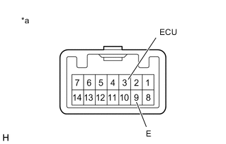
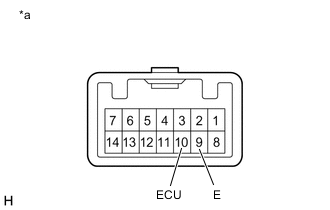
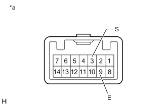
*a Component without harness connected
(HV/EV Mode Switch (Pattern Select Switch Assembly))
Inspect HV/EV mode switch (pattern select switch assembly)
-
Measure the resistance according to the value(s) in the table below.
Standard Resistance Tester Connection Condition Specified Condition 3 (ECU) - 9 (E) HV/EV mode switch (pattern select switch assembly) being pushed and held Below 50 Ω HV/EV mode switch (pattern select switch assembly) not pushed 10 kΩ or higher If the result is not as specified, replace the pattern select switch assembly.
-
-
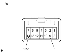
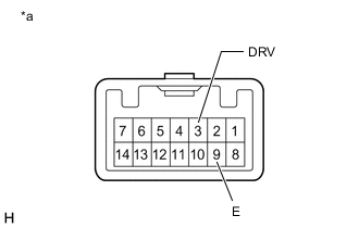
*a Component without harness connected
(Drive Mode Select Switch (Pattern Select Switch Assembly))
Inspect drive mode select switch (pattern select switch assembly)
-
Measure the resistance according to the value(s) in the table below.
Standard Resistance Tester Connection Condition Specified Condition 14 (DRV) - 9 (E) Drive mode select switch (pattern select switch assembly) being pushed and held Below 50 Ω Drive mode select switch (pattern select switch assembly) not pushed 10 kΩ or higher If the result is not as specified, replace the pattern select switch assembly.
-
-
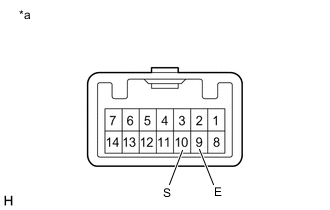
*a Component without harness connected
(EV Auto Switch (Pattern Select Switch Assembly))
Inspect EV auto switch (pattern select switch assembly)
-
Measure the resistance according to the value(s) in the table below.
Standard Resistance Tester Connection Condition Specified Condition 10 (S) - 9 (E) EV auto switch (pattern select switch assembly) being pushed and held Below 50 Ω EV auto switch (pattern select switch assembly) not pushed 10 kΩ or higher If the result is not as specified, replace the pattern select switch assembly.
-
-
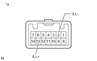
*a Component without harness connected
(Pattern Select Switch Assembly)
Inspect illumination
-
Apply auxiliary battery voltage between the terminals of the switch, and check the illumination condition of the pattern select switch assembly.
OK Measurement Condition Specified Condition Auxiliary Battery positive (+) → 13 (ILL+)
Auxiliary Battery negative (-) → 2 (ILL-)
Illuminates If the result is not as specified, replace the pattern select switch assembly.
-
-
-
w/ EV City Switch:
-
*a Component without harness connected
(HV/EV Mode Switch (Pattern Select Switch Assembly))
Inspect HV/EV mode switch (pattern select switch assembly)
-
Measure the resistance according to the value(s) in the table below.
Standard Resistance Tester Connection Condition Specified Condition 3 (ECU) - 9 (E) HV/EV mode switch (pattern select switch assembly) being pushed and held Below 50 Ω HV/EV mode switch (pattern select switch assembly) not pushed 10 kΩ or higher If the result is not as specified, replace the pattern select switch assembly.
-
-
*a Component without harness connected
(Drive Mode Select Switch (Pattern Select Switch Assembly))
Inspect drive mode select switch (pattern select switch assembly)
-
Measure the resistance according to the value(s) in the table below.
Standard Resistance Tester Connection Condition Specified Condition 14 (DRV) - 9 (E) Drive mode select switch (pattern select switch assembly) being pushed and held Below 50 Ω Drive mode select switch (pattern select switch assembly) not pushed 10 kΩ or higher If the result is not as specified, replace the pattern select switch assembly.
-
-
*a Component without harness connected
(EV City Switch (Pattern Select Switch Assembly))
Inspect EV City switch (pattern select switch assembly)
-
Measure the resistance according to the value(s) in the table below.
Standard Resistance Tester Connection Condition Specified Condition 10 (S) - 9 (E) EV City switch (pattern select switch assembly) being pushed and held Below 50 Ω EV City switch (pattern select switch assembly) not pushed 10 kΩ or higher If the result is not as specified, replace the pattern select switch assembly.
-
-
*a Component without harness connected
(Pattern Select Switch Assembly)
Inspect illumination
-
Apply auxiliary battery voltage between the terminals of the switch, and check the illumination condition of the pattern select switch assembly.
OK Measurement Condition Specified Condition Auxiliary Battery positive (+) → 13 (ILL+)
Auxiliary Battery negative (-) → 2 (ILL-)
Illuminates If the result is not as specified, replace the pattern select switch assembly.
-
-
-
w/ Vehicle Approaching Speaker Switch:
-
*a Component without harness connected
(HV/EV Mode Switch (Pattern Select Switch Assembly))
Inspect HV/EV mode switch (pattern select switch assembly)
-
Measure the resistance according to the value(s) in the table below.
Standard Resistance Tester Connection Condition Specified Condition 10 (ECU) - 9 (E) HV/EV mode switch (pattern select switch assembly) being pushed and held Below 50 Ω HV/EV mode switch (pattern select switch assembly) not pushed 10 kΩ or higher If the result is not as specified, replace the pattern select switch assembly.
-
-
*a Component without harness connected
(Drive Mode Select Switch (Pattern Select Switch Assembly))
Inspect drive mode select switch (pattern select switch assembly)
-
Measure the resistance according to the value(s) in the table below.
Standard Resistance Tester Connection Condition Specified Condition 3 (DRV) - 9 (E) Drive mode select switch (pattern select switch assembly) being pushed and held Below 50 Ω Drive mode select switch (pattern select switch assembly) not pushed 10 kΩ or higher If the result is not as specified, replace the pattern select switch assembly.
-
-
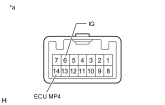
*a Component without harness connected
(Vehicle Approaching Speaker Switch (Pattern Select Switch Assembly))
Inspect vehicle approaching speaker switch (pattern select switch assembly)
-
Measure the resistance according to the value(s) in the table below.
Standard Resistance Tester Connection Condition Specified Condition 6 (IG) - 14 (ECU MP4) Vehicle approaching speaker switch (pattern select switch assembly) being pushed and held Below 50 Ω Vehicle approaching speaker switch (pattern select switch assembly) not pushed 10 kΩ or higher If the result is not as specified, replace the pattern select switch assembly.
-
-
*a Component without harness connected
(Pattern Select Switch Assembly)
Inspect illumination
-
Apply auxiliary battery voltage between the terminals of the switch, and check the illumination condition of the pattern select switch assembly.
OK Measurement Condition Specified Condition Auxiliary Battery positive (+) → 13 (ILL+)
Auxiliary Battery negative (-) → 2 (ILL-)
Illuminates If the result is not as specified, replace the pattern select switch assembly.
-
-
-
-
INSPECT PATTERN SELECT SWITCH ASSEMBLY (for RHD)
-
Inspect HV/EV mode switch (pattern select switch assembly)
-

*a Component without harness connected
(HV/EV Mode Switch (Pattern Select Switch Assembly))
Measure the resistance according to the value(s) in the table below.
Standard Resistance Tester Connection Condition Specified Condition 14 (ECU) - 9 (E) HV/EV mode switch (pattern select switch assembly) being pushed and held Below 50 Ω HV/EV mode switch (pattern select switch assembly) not pushed 10 kΩ or higher If the result is not as specified, replace the pattern select switch assembly.
-
-
Inspect drive mode select switch (pattern select switch assembly)
-
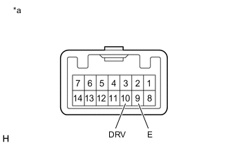
*a Component without harness connected
(Drive Mode Select Switch (Pattern Select Switch Assembly))
Measure the resistance according to the value(s) in the table below.
Standard Resistance Tester Connection Condition Specified Condition 10 (DRV) - 9 (E) Drive mode select switch (pattern select switch assembly) being pushed and held Below 50 Ω Drive mode select switch (pattern select switch assembly) not pushed 10 kΩ or higher If the result is not as specified, replace the pattern select switch assembly.
-
-
Inspect EV City switch (pattern select switch assembly)
-
*a Component without harness connected
(EV City Switch (Pattern Select Switch Assembly))
Measure the resistance according to the value(s) in the table below.
Standard Resistance Tester Connection Condition Specified Condition 3 (S) - 9 (E) EV City switch (pattern select switch assembly) being pushed and held Below 50 Ω EV City switch (pattern select switch assembly) not pushed 10 kΩ or higher If the result is not as specified, replace the pattern select switch assembly.
-
-
Inspect illumination
-
*a Component without harness connected
(Pattern Select Switch Assembly)
Apply auxiliary battery voltage between the terminals of the switch, and check the illumination condition of the pattern select switch assembly.
OK Measurement Condition Specified Condition Auxiliary Battery positive (+) → 13 (ILL+)
Auxiliary Battery negative (-) → 2 (ILL-)
Illuminates If the result is not as specified, replace the pattern select switch assembly.
-
-