HV RELAY ASSEMBLY INSTALLATION
PROCEDURE
-
INSTALL HV BATTERY JUNCTION BLOCK ASSEMBLY
CAUTION:
Be sure to wear insulated gloves and protective goggles.
-
No. 2 HV battery junction block assembly:
-
Install the No. 2 HV battery junction block assembly to the HV battery with the 4 nuts.
- Torque:
- 7.5 N*m { 76 kgf*cm, 66 in.*lbf }
Note
If the No. 2 HV battery junction block assembly has been struck or dropped, replace it with a new one.
-
Engage the 2 clamps.
-
Connect the 4 No. 2 HV battery junction block assembly connectors.
Note
Make sure that the connectors are connected securely.
-
-
No. 1 HV battery junction block assembly:
-
Install the No. 1 HV battery junction block assembly to the HV battery with the 5 nuts.
- Torque:
- 7.5 N*m { 76 kgf*cm, 66 in.*lbf }
Note
If the No. 1 HV battery junction block assembly has been struck or dropped, replace it with a new one.
-
Connect the 4 No. 1 HV battery junction block assembly connectors.
Note
Make sure that the connectors are connected securely.
-
-
-
CONNECT WIRE HARNESS
CAUTION:
Be sure to wear insulated gloves and protective goggles.
-
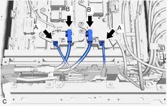
Connect the 2 HV battery junction block assembly connectors (B).
Note
Make sure that the connectors are connected securely.
-
Connect the 2 HV battery junction block assembly connectors (A).
Note
Make sure that the connectors are connected securely.
-
-
INSTALL UPPER HYBRID BATTERY COVER SUB-ASSEMBLY
CAUTION:
Be sure to wear insulated gloves and protective goggles.
-
Install the upper hybrid battery cover sub-assembly to the HV battery with the 12 bolts and 8 nuts.
- Torque:
- 7.5 N*m { 76 kgf*cm, 66 in.*lbf }
-
-
INSTALL NO. 2 HV BATTERY SHIELD PANEL
-
INSTALL NO. 3 HV BATTERY SHIELD PANEL
-
INSTALL NO. 1 HV BATTERY SHIELD PANEL
-
INSTALL REAR FLOOR FRONT BATTERY COVER BOARD
-
INSTALL REAR SEAT CONSOLE BOX ASSEMBLY
-
INSTALL DECK TRIM SIDE PANEL ASSEMBLY RH
-
INSTALL NO. 1 LUGGAGE COMPARTMENT LIGHT ASSEMBLY
-
INSTALL TONNEAU COVER HOOK A (for RH Side with Toyota Safety Sense)
-
INSTALL NO. 1 TONNEAU COVER HOLDER CAP (for RH Side with Toyota Safety Sense)
-
INSTALL NO. 2 ROPE HOOK (for RH Side without Toyota Safety Sense)
-
INSTALL ROPE HOOK (for RH Side without Toyota Safety Sense)
-
INSTALL REAR SEAT SIDE GARNISH LH
-
INSTALL REAR SEATBACK HINGE SUB-ASSEMBLY LH
-
INSTALL REAR DOOR OPENING TRIM WEATHERSTRIP LH
-
INSTALL REAR SEAT SIDE GARNISH RH
-
INSTALL REAR SEATBACK HINGE SUB-ASSEMBLY RH
-
INSTALL REAR DOOR OPENING TRIM WEATHERSTRIP RH
-
INSTALL REAR SEATBACK ASSEMBLY LH
-
INSTALL REAR SEATBACK ASSEMBLY RH
-
INSTALL REAR SEATBACK HINGE COVER
-
INSTALL REAR SEAT HEADREST ASSEMBLY (for LH Side)
-
INSTALL REAR SEAT HEADREST ASSEMBLY (for RH Side)
-
INSTALL REAR DECK TRIM COVER
-
INSTALL DECK TRIM SERVICE HOLE COVER
-
INSTALL DECK FLOOR BOX LH
-
INSTALL DECK FLOOR BOX RH
-
INSTALL REAR NO. 4 FLOOR BOARD
-
INSTALL REAR NO. 3 FLOOR BOARD
-
INSTALL TONNEAU COVER ASSEMBLY
-
INSTALL SERVICE PLUG GRIP
-
PERFORM CURRENT SENSOR OFFSET LEARNING
Tech Tips
Perform this procedure when the HV battery junction block assembly or battery ECU assembly has been replaced.
-
Connect the GTS to the DLC3.
-
Turn the power switch on (READY).
-
Perform a road test.
Note
Accelerate and decelerate gently. Avoid rapid acceleration and deceleration.
-
Enter the following menus: Powertrain / HV Battery / Data List / Hybrid Battery Current.
Powertrain > HV Battery > Data ListTester Display Hybrid Battery Current -
Drive the vehicle with the value of Data List item "Hybrid Battery Current" between -50 A and 50 A.
Tech Tips
Distance and driving time are not specified.
-
Turn the power switch off and leave the vehicle for 30 seconds or more.
-
Turn the power switch on (IG).
-
Enter the following menus: Powertrain / HV Battery / Data List / Hybrid Battery Current.
Powertrain > HV Battery > Data ListTester Display Hybrid Battery Current -
Check that the value of "Hybrid Battery Current" is between -0.5 A and 0.5 A with the power switch on (IG).
Note
If the value is outside the specified range, perform the road test again.
Tech Tips
-
When the power switch is on (IG), if value of "Hybrid Battery Current" is between -0.5 A and 0.5 A, current sensor offset learning has been completed.
-
Even if the current sensor offset learning is not complete, the current sensor value will be corrected by repeating the road test a maximum of 7 times.
-
-
-