FRAME WIRE INSTALLATION
PROCEDURE
-
INSTALL HV BATTERY CHARGER WIRE (w/o Solar Charging System)
CAUTION:
Wear insulated gloves.
-
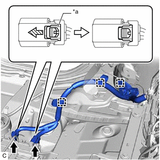
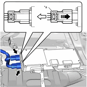
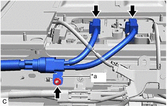
*a Green-colored Lock 
Slide Engage the 3 clamps to install the HV battery charger wire.
-
Connect the 2 electric vehicle charger assembly connectors and slide the green-colored lock as shown in the illustration to lock it securely.
Note
Make sure that the connectors are connected securely.
-
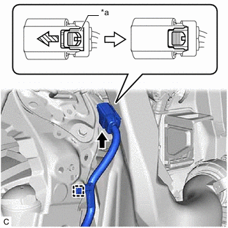
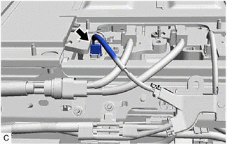
*a Green-colored Lock Slide Engage the clamp.
-
Connect the inlet AC charger cable connector and slide the green-colored lock as shown in the illustration to lock it securely.
Note
Make sure that the connector is connected securely.
-
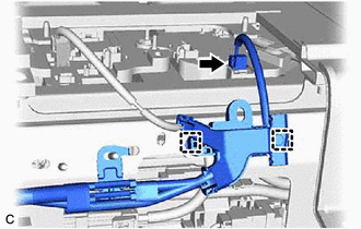
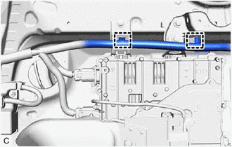
Engage the 2 clamps to connect the HV battery charger wire.
-
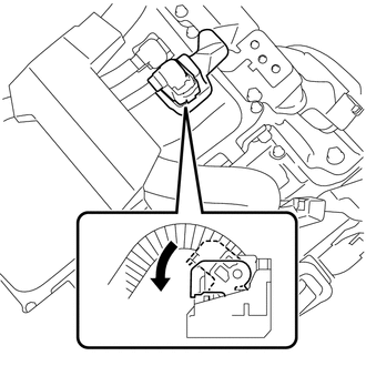
Connect the HV battery junction block assembly connector.
Note
Make sure that the connector is connected securely.
-
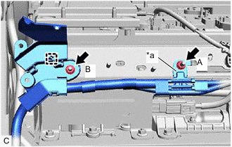
*a Earth Terminal Engage the clamp.
-
Install the nut (B).
- Torque:
- 8.0 N*m { 82 kgf*cm, 71 in.*lbf }
-
Install the nut (A) to connect the earth terminal.
- Torque:
- 8.0 N*m { 82 kgf*cm, 71 in.*lbf }
-
-
INSTALL HV BATTERY CHARGER WIRE (w/ Solar Charging System)
CAUTION:
Wear insulated gloves.
-
*a Green-colored Lock Slide Engage the 3 clamps to install the HV battery charger wire.
-
Connect the 2 electric vehicle charger assembly connectors and slide the green-colored lock as shown in the illustration to lock it securely.
Note
Make sure that the connectors are connected securely.
-
*a Green-colored Lock 
Connect in this direction. Connect the 2 solar energy control unit connectors as shown in the illustration and check that the green-colored lock of each connector is securely locked.
Note
Make sure that the connectors are connected securely.
-
Engage the 2 clamps.
-
*a Green-colored Lock Slide Engage the clamp.
-
Connect the inlet AC charger cable connector and slide the green-colored lock as shown in the illustration to lock it securely.
Note
Make sure that the connector is connected securely.
-
Engage the 2 clamps to connect the HV battery charger wire.
-
Connect the HV battery junction block assembly connector.
Note
Make sure that the connector is connected securely.
-
*a Earth Terminal Engage the clamp.
-
Install the nut (B).
- Torque:
- 8.0 N*m { 82 kgf*cm, 71 in.*lbf }
-
Install the nut (A) to connect the earth terminal.
- Torque:
- 8.0 N*m { 82 kgf*cm, 71 in.*lbf }
-
-
INSTALL HV FLOOR UNDER WIRE
CAUTION:
Wear insulated gloves.
-
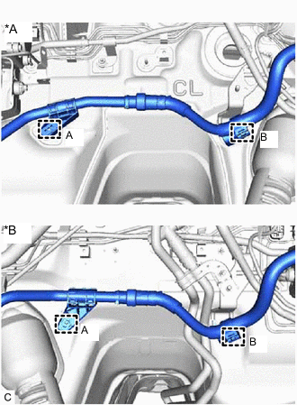
*A for LHD *B for RHD Engage the clamp (B) to install the HV floor under wire.
-
Install a new clamp (A).
-
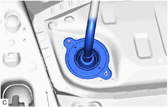
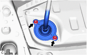
Insert the HV floor under wire into the floor panel hole and engage the grommet.
-
Install 3 new clamps in the order shown in the illustration.
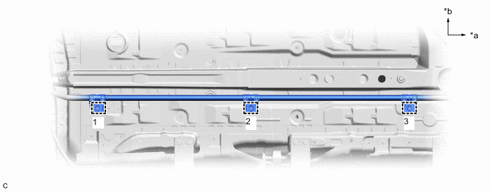
*a Front of Vehicle *b RH Side -
Install the 2 nuts.
- Torque:
- 8.5 N*m { 87 kgf*cm, 75 in.*lbf }
-
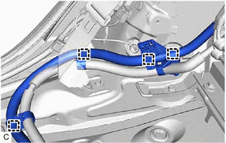
Engage the 4 clamps.
-
Engage the 2 claws to close the wire harness clamp.
-
*a Earth Terminal Install the nut to connect the earth terminal.
- Torque:
- 8.0 N*m { 82 kgf*cm, 71 in.*lbf }
-
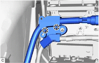
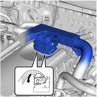
Connect the 2 HV battery junction block assembly connectors.
Note
Make sure that the connectors are connected securely.
-
-
CONNECT HV BATTERY CHARGER WIRE
CAUTION:
Wear insulated gloves.
-
Connect the HV battery junction block assembly connector.
Note
Make sure that the connector is connected securely.
-
-
CONNECT NO. 2 PARKING BRAKE CABLE ASSEMBLY
-
Connect the No. 2 parking brake cable assembly with the 2 bolts.
- Torque:
- 6.0 N*m { 61 kgf*cm, 53 in.*lbf }
-
-
INSTALL FRONT SUSPENSION CROSSMEMBER SUB-ASSEMBLY
-
INSTALL FRONT FLOOR COVER RH
-
INSTALL NO. 1 FLOOR UNDER COVER ASSEMBLY
-
INSTALL NO. 1 HV BATTERY SHIELD PANEL
-
INSTALL REAR SEAT CUSHION LEG SUB-ASSEMBLY
-
INSTALL REAR FLOOR FRONT BATTERY COVER BOARD
-
INSTALL REAR SEAT CONSOLE BOX ASSEMBLY
-
INSTALL DECK TRIM SIDE PANEL ASSEMBLY RH
-
INSTALL NO. 1 LUGGAGE COMPARTMENT LIGHT ASSEMBLY
-
INSTALL TONNEAU COVER HOOK A (for RH Side with Toyota Safety Sense)
-
INSTALL NO. 1 TONNEAU COVER HOLDER CAP (for RH Side with Toyota Safety Sense)
-
INSTALL NO. 2 ROPE HOOK (for RH Side without Toyota Safety Sense)
-
INSTALL ROPE HOOK (for RH Side without Toyota Safety Sense)
-
INSTALL REAR SEAT SIDE GARNISH LH
-
INSTALL REAR SEATBACK HINGE SUB-ASSEMBLY LH
-
INSTALL REAR DOOR OPENING TRIM WEATHERSTRIP LH
-
INSTALL REAR SEAT SIDE GARNISH RH
-
INSTALL REAR SEATBACK HINGE SUB-ASSEMBLY RH
-
INSTALL REAR DOOR OPENING TRIM WEATHERSTRIP RH
-
INSTALL REAR SEATBACK ASSEMBLY LH
-
INSTALL REAR SEATBACK ASSEMBLY RH
-
INSTALL REAR SEATBACK HINGE COVER
-
INSTALL REAR SEAT HEADREST ASSEMBLY (for LH Side)
-
INSTALL REAR SEAT HEADREST ASSEMBLY (for RH Side)
-
INSTALL REAR DECK TRIM COVER
-
INSTALL DECK TRIM SERVICE HOLE COVER
-
INSTALL DECK FLOOR BOX LH
-
INSTALL DECK FLOOR BOX RH
-
INSTALL REAR NO. 4 FLOOR BOARD
-
INSTALL REAR NO. 3 FLOOR BOARD
-
INSTALL TONNEAU COVER ASSEMBLY
-
CONNECT HV FLOOR UNDER WIRE
-
CONNECT ENGINE WIRE (w/ Canister Pump Module)
CAUTION:
Wear insulated gloves.
Note
Do not allow any foreign matter or water to enter the inverter with converter assembly.
-
Connect the inverter with converter assembly connector and move the lock lever as shown in the illustration.
Note
-
To prevent damage due to static electricity, do not touch the terminals of the disconnected connectors.
-
Do not damage the terminals, connector housing or inverter with converter assembly when connecting the connectors.
-
Do not touch the waterproof seal or terminals of the connector.
-
-
-
CONNECT ENGINE WIRE (w/o Canister Pump Module)
CAUTION:
Wear insulated gloves.
Note
Do not allow any foreign matter or water to enter the inverter with converter assembly.
-
Engage the 2 clamps and connect the engine wire.
-
Install the bolt.
- Torque:
- 8.0 N*m { 82 kgf*cm, 71 in.*lbf }
-
Connect the 2 inverter with converter assembly connectors and move each lock lever as shown in the illustration.
Note
-
To prevent damage due to static electricity, do not touch the terminals of the disconnected connectors.
-
Do not damage the terminals, connector housing or inverter with converter assembly when connecting the connectors.
-
Do not touch the waterproof seal or terminals of the connector.
-
-
-
INSTALL NO. 1 ENGINE COVER SUB-ASSEMBLY (w/o Canister Pump Module)
-
INSTALL OUTER COWL TOP PANEL SUB-ASSEMBLY
-
INSTALL COWL BODY MOUNTING REINFORCEMENT LH
-
INSTALL WATER GUARD PLATE
-
INSTALL NO. 1 HEATER AIR DUCT SPLASH SHIELD SEAL (for LHD)
-
INSTALL NO. 2 HEATER AIR DUCT SPLASH SHIELD SEAL (for RHD)
-
INSTALL WINDSHIELD WIPER MOTOR AND LINK ASSEMBLY
-
INSTALL SERVICE PLUG GRIP