FRAME WIRE REMOVAL
CAUTION / NOTICE / HINT
The necessary procedures (adjustment, calibration, initialization, or registration) that must be performed after parts are removed and installed, or replaced during HV floor under wire removal/installation are shown below.
| Replaced Part or Performed Procedure | Necessary Procedures | Effect/Inoperative Function when Necessary Procedure not Performed | Link |
|---|---|---|---|
| Auxiliary battery terminal is disconnected/reconnected | Memorize steering angle neutral point | Lane departure alert system (w/ Steering Control) | |
| Intelligent clearance sonar system*1 | |||
| Simple intelligent parking assist system*1 | |||
| Pre-crash safety system | |||
| Adaptive high beam system | |||
| Parking assist monitor system | |||
| Initialize back door lock | Power door lock control system | ||
| Front wheel alignment adjustment |
|
|
|
| Suspension, tires, etc. (The vehicle height changes because of suspension or tire replacement) |
|
|
|
| Rear television camera assembly optical axis (Back camera position setting) | Parking assist monitor system | ||
| Initialize No. 1 headlight ECU sub-assembly LH |
|
Click here Click here
*2: w/ Adaptive High Beam System
CAUTION:
-
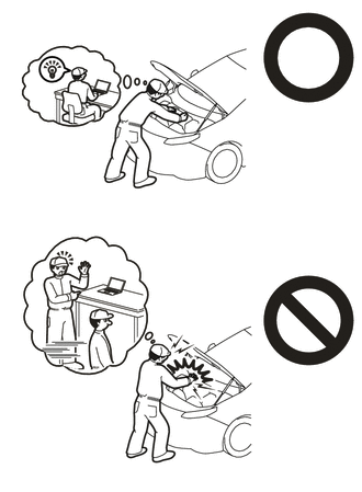
Orange wire harnesses and connectors indicate high-voltage circuits. To prevent electric shock, always follow the procedure described in the repair manual.
-

To prevent electric shock, wear insulated gloves when working on wire harnesses and components of the high voltage system.
PROCEDURE
-
PRECAUTION
Note
After turning the power switch off, waiting time may be required before disconnecting the cable from the negative (-) auxiliary battery terminal. Therefore, make sure to read the disconnecting the cable from the negative (-) auxiliary battery terminal notices before proceeding with work.
-
REMOVE SERVICE PLUG GRIP
-
REMOVE WINDSHIELD WIPER MOTOR AND LINK ASSEMBLY
-
REMOVE NO. 1 HEATER AIR DUCT SPLASH SHIELD SEAL (for LHD)
-
REMOVE NO. 2 HEATER AIR DUCT SPLASH SHIELD SEAL (for RHD)
-
REMOVE WATER GUARD PLATE
-
REMOVE COWL BODY MOUNTING REINFORCEMENT LH
-
REMOVE OUTER COWL TOP PANEL SUB-ASSEMBLY
-
REMOVE NO. 1 ENGINE COVER SUB-ASSEMBLY (w/o Canister Pump Module)
-
DISCONNECT ENGINE WIRE (w/o Canister Pump Module)
CAUTION:
Wear insulated gloves.
Note
Do not allow any foreign matter or water to enter the inverter with converter assembly.
-
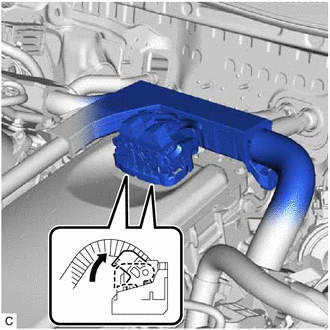
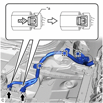
Move each lock lever as shown in the illustration and disconnect the 2 inverter with converter assembly connectors.
Note
-
Do not damage the terminals, connector housing or inverter with converter assembly during disconnection.
-
Cover the hole where the cable was connected with tape (non-residue type) or equivalent to prevent entry of foreign matter.
-
Insulate the disconnected terminals with insulating tape.
-
Do not touch the waterproof seal or terminals of the connector.
-
-
Remove the bolt.
-
Disengage the 2 clamps and disconnect the engine wire.
-
-
DISCONNECT ENGINE WIRE (w/ Canister Pump Module)
CAUTION:
Wear insulated gloves.
Note
Do not allow any foreign matter or water to enter the inverter with converter assembly.
-
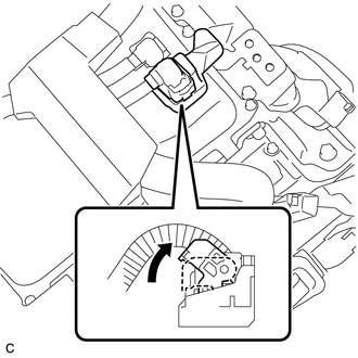
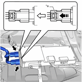
Move the lock lever as shown in the illustration and disconnect the inverter with converter assembly connector.
Note
-
Do not damage the terminals, connector housing or inverter with converter assembly during disconnection.
-
Cover the hole where the cable was connected with tape (non-residue type) or equivalent to prevent entry of foreign matter.
-
Insulate the disconnected terminals with insulating tape.
-
Do not touch the waterproof seal or terminals of the connector.
-
-
-
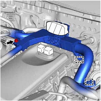
REMOVE CONNECTOR COVER ASSEMBLY
-
CHECK TERMINAL VOLTAGE
-
TEMPORARILY INSTALL CONNECTOR COVER ASSEMBLY
-
DISCONNECT HV FLOOR UNDER WIRE
-
REMOVE TONNEAU COVER ASSEMBLY
-
REMOVE REAR NO. 3 FLOOR BOARD
-
REMOVE REAR NO. 4 FLOOR BOARD
-
REMOVE DECK FLOOR BOX LH
-
REMOVE DECK FLOOR BOX RH
-
REMOVE DECK TRIM SERVICE HOLE COVER
-
REMOVE REAR DECK TRIM COVER
-
REMOVE REAR SEAT HEADREST ASSEMBLY (for LH Side)
-
REMOVE REAR SEAT HEADREST ASSEMBLY (for RH Side)
-
REMOVE REAR SEATBACK ASSEMBLY LH
-
REMOVE REAR SEATBACK HINGE COVER
-
REMOVE REAR SEATBACK ASSEMBLY RH
-
DISCONNECT REAR DOOR OPENING TRIM WEATHERSTRIP LH
-
REMOVE REAR SEATBACK HINGE SUB-ASSEMBLY LH
-
REMOVE REAR SEAT SIDE GARNISH LH
-
DISCONNECT REAR DOOR OPENING TRIM WEATHERSTRIP RH
-
REMOVE REAR SEATBACK HINGE SUB-ASSEMBLY RH
-
REMOVE REAR SEAT SIDE GARNISH RH
-
REMOVE ROPE HOOK (for RH Side without Toyota Safety Sense)
-
REMOVE NO. 2 ROPE HOOK (for RH Side without Toyota Safety Sense)
-
REMOVE NO. 1 TONNEAU COVER HOLDER CAP (for RH Side with Toyota Safety Sense)
-
REMOVE TONNEAU COVER HOOK A (for RH Side with Toyota Safety Sense)
-
REMOVE NO. 1 LUGGAGE COMPARTMENT LIGHT ASSEMBLY
-
REMOVE DECK TRIM SIDE PANEL ASSEMBLY RH
-
REMOVE REAR SEAT CONSOLE BOX ASSEMBLY
-
REMOVE REAR FLOOR FRONT BATTERY COVER BOARD
-
REMOVE REAR SEAT CUSHION LEG SUB-ASSEMBLY
-
REMOVE NO. 1 HV BATTERY SHIELD PANEL
-
REMOVE NO. 1 FLOOR UNDER COVER ASSEMBLY
-
REMOVE FRONT FLOOR COVER RH
-
REMOVE FRONT SUSPENSION CROSSMEMBER SUB-ASSEMBLY
-
REMOVE NO. 2 PARKING BRAKE CABLE ASSEMBLY
-
Remove the 2 bolts and disconnect the No. 2 parking brake cable assembly.
-
-
DISCONNECT HV BATTERY CHARGER WIRE
CAUTION:
Wear insulated gloves.
Note
Insulate each disconnected high-voltage connector with insulating tape. Wrap the connector from the wire harness side to the end of the connector.
-
Disconnect the HV battery junction block assembly connector.
-
-
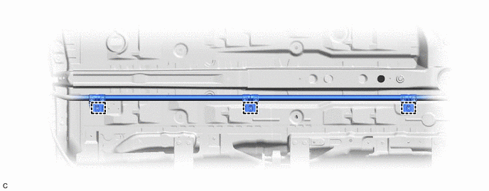
REMOVE HV FLOOR UNDER WIRE
CAUTION:
Wear insulated gloves.
Note
Insulate each disconnected high-voltage connector with insulating tape. Wrap the connector from the wire harness side to the end of the connector.
-
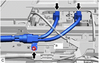
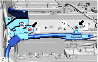
*a Earth Terminal Disconnect the 2 HV battery junction block assembly connectors.
-
Remove the nut and disconnect the earth terminal.
-
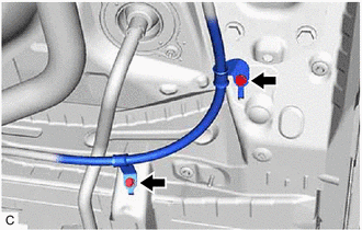
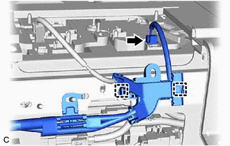
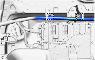
Disengage the 2 claws and open the wire harness clamp.
-
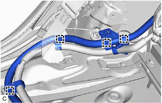
Disengage the 4 clamps.
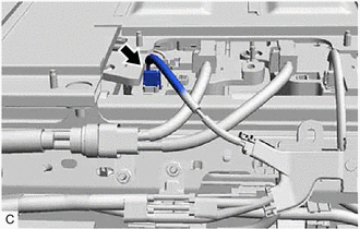
-
Remove the 2 nuts.
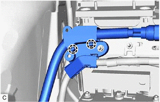
-
Remove the 3 clamps.
Note
If the clamps are removed forcibly, the stud bolts may be damaged.
-
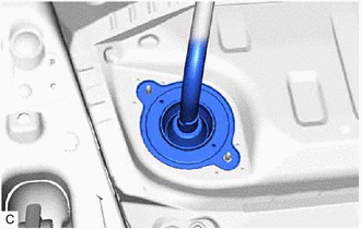
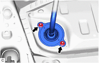
Disengage the grommet and pull out the HV floor under wire from the floor panel hole.
-
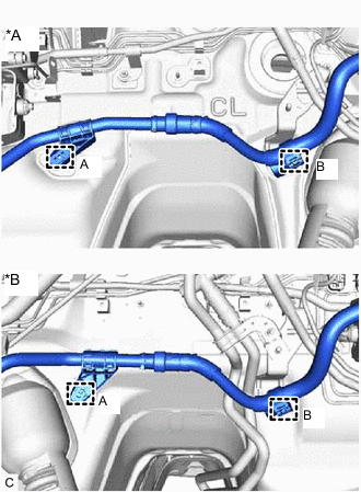
*A for LHD *B for RHD Remove the clamp (A).
-
Disengage the clamp (B) to remove the HV floor under wire.
-
-
REMOVE HV BATTERY CHARGER WIRE (w/o Solar Charging System)
CAUTION:
Wear insulated gloves.
Note
Insulate the disconnected connectors with insulating tape.
-
*a Earth Terminal Remove the nut (A) and disconnect the earth terminal.
-
Remove the nut (B).
-
Disengage the clamp.
-
Disconnect the HV battery junction block assembly connector.
-
Disengage the 2 clamps to disconnect the HV battery charger wire.
-
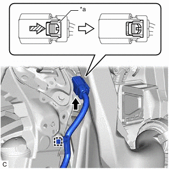
*a Green-colored Lock 
Slide Using a screwdriver, slide the green-colored lock of the connector as shown in the illustration to release it and disconnect the inlet AC charger cable connector.
-
Disengage the clamp.
-
*a Green-colored Lock Slide Using a screwdriver, slide the green-colored lock of the connector as shown in the illustration to release it and disconnect the 2 electric vehicle charger assembly connectors.
-
Disengage the 3 clamps to remove the HV battery charger wire.
-
-
REMOVE HV BATTERY CHARGER WIRE (w/ Solar Charging System)
CAUTION:
Wear insulated gloves.
Note
Insulate the disconnected connectors with insulating tape.
-
*a Earth Terminal Remove the nut (A) and disconnect the earth terminal.
-
Remove the nut (B).
-
Disengage the clamp.
-
Disconnect the HV battery junction block assembly connector.
-
Disengage the 2 clamps to disconnect the HV battery charger wire.
-
*a Green-colored Lock Slide Using a screwdriver, slide the green-colored lock of the connector as shown in the illustration to release it and disconnect the inlet AC charger cable connector.
-
Disengage the clamp.
-
Disengage the 2 clamps.
-
*a Screwdriver Insertion Position 
Release in this direction. Insert the screwdriver at the position shown in the illustration to release the green-colored lock of each connector and disconnect each solar energy control unit connector.
-
*a Green-colored Lock Slide Using a screwdriver, slide the green-colored lock of the connector as shown in the illustration to release it and disconnect the 2 electric vehicle charger assembly connectors.
-
Disengage the 3 clamps to remove the HV battery charger wire.
-