HV BATTERY REMOVAL
CAUTION / NOTICE / HINT
The necessary procedures (adjustment, calibration, initialization, or registration) that must be performed after parts are removed and installed, or replaced during HV battery removal/installation are shown below.
| Replaced Part or Performed Procedure | Necessary Procedures | Effect/Inoperative Function when Necessary Procedure not Performed | Link |
|---|---|---|---|
| Auxiliary battery terminal is disconnected/reconnected | Memorize steering angle neutral point | Lane departure alert system (w/ Steering Control) | |
| Intelligent clearance sonar system*1 | |||
| Simple intelligent parking assist system*1 | |||
| Pre-crash safety system | |||
| Adaptive high beam system | |||
| Parking assist monitor system | |||
| Initialize back door lock | Power door lock control system | ||
| Replacement of HV battery |
|
HV battery status information cannot be updated | |
| Replacement of hybrid battery terminal block | Perform high voltage fuse accumulated load history reset | DTCs are stored | |
|
Current sensor offset learning |
Click here Click here
CAUTION:
-
Orange wire harnesses and connectors indicate high-voltage circuits. To prevent electric shock, always follow the procedure described in the repair manual.
-

To prevent electric shock, wear insulated gloves when working on wire harnesses and components of the high voltage system.
Tech Tips
When disposing of an HV battery, make sure to return it through an authorized collection agent who is capable of handling it safely. If the HV battery is returned via the manufacturer specified route, it will be returned properly and in a safe manner by an authorized collection agent.
PROCEDURE
-
PRECAUTION
Note
-
After turning the power switch off, waiting time may be required before disconnecting the cable from the negative (-) auxiliary battery terminal. Therefore, make sure to read the disconnecting the cable from the negative (-) auxiliary battery terminal notices before proceeding with work.
-
When the cable is disconnected from the negative (-) auxiliary battery terminal, some systems need to be initialized after the cable is reconnected.
-
If the HV battery has been struck or dropped, replace it.
-
When connecting a connector to the HV battery, confirm that the connector is securely connected through the following:
- Push the connector until a click sound is heard.
- Visually check and confirm that the connector is securely connected by pulling on it.
-
Make sure to insulate the high-voltage connectors and terminals of the HV battery with insulating tape after removing it.
If the HV battery stored without insulating the connectors and terminals, electric shock or fire may result.
-
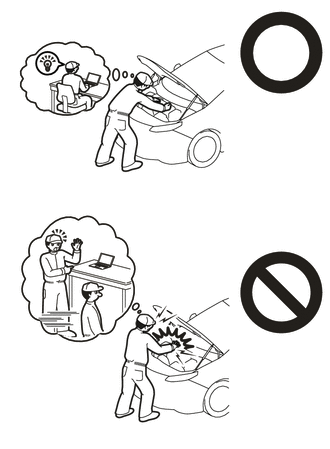
Do not touch any high voltage wire harnesses, connectors or parts with bare hands.
-
Do not allow foreign matter, such as grease or oil, to adhere to the bolts or nuts of the HV battery.
-
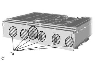
*a Opening Do not put your hands into the openings of the HV battery.
-
When removing/installing/moving the HV battery, make sure not to tilt it more than 80°.
-
Do not climb on top of or stand on the HV battery.
-
Do not allow any foreign matter or water to enter the HV battery.
-
-
READ VALUE USING GTS
-
Connect the GTS to the DLC3.
-
Turn the power switch on (IG).
-
Enter the following menus: Powertrain / HV Battery / Data List / Hybrid Battery Temperature 1 to 15.
Powertrain > HV Battery > Data ListTester Display Hybrid Battery Temperature 1 Hybrid Battery Temperature 2 Hybrid Battery Temperature 3 Hybrid Battery Temperature 4 Hybrid Battery Temperature 5 Hybrid Battery Temperature 6 Hybrid Battery Temperature 7 Hybrid Battery Temperature 8 Hybrid Battery Temperature 9 Hybrid Battery Temperature 10 Hybrid Battery Temperature 11 Hybrid Battery Temperature 12 Hybrid Battery Temperature 13 Hybrid Battery Temperature 14 Hybrid Battery Temperature 15 -
Read the Data List.
Note
If any of the temperatures listed in "Hybrid Battery Temperature 1 to 15" are 50°C (122°F) or more, leave the vehicle until the temperature drops to less than 50°C (122°F).
-
-
REMOVE SERVICE PLUG GRIP
-
REMOVE WINDSHIELD WIPER MOTOR AND LINK ASSEMBLY
-
REMOVE NO. 1 HEATER AIR DUCT SPLASH SHIELD SEAL (for LHD)
-
REMOVE NO. 2 HEATER AIR DUCT SPLASH SHIELD SEAL (for RHD)
-
REMOVE WATER GUARD PLATE
-
REMOVE COWL BODY MOUNTING REINFORCEMENT LH
-
REMOVE OUTER COWL TOP PANEL SUB-ASSEMBLY
-
REMOVE NO. 1 ENGINE COVER SUB-ASSEMBLY (w/o Canister Pump Module)
-
DISCONNECT ENGINE WIRE (w/o Canister Pump Module)
-
DISCONNECT ENGINE WIRE (w/ Canister Pump Module)
-
REMOVE CONNECTOR COVER ASSEMBLY
-
CHECK TERMINAL VOLTAGE
-
INSTALL CONNECTOR COVER ASSEMBLY
CAUTION:
Wear insulated gloves.
-
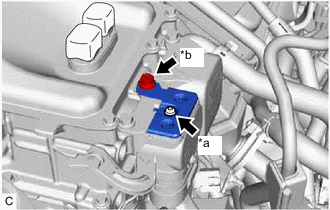
*a Bolt (A) *b Bolt (B) Using a T25 "TORX" socket wrench, install the connector cover assembly to the inverter with converter assembly with the bolt (A).
- Torque:
- 4.5 N*m { 46 kgf*cm, 40 in.*lbf }
Note
Do not touch the waterproof seal of the connector cover assembly.
-
Install the bolt (B).
- Torque:
- 8.0 N*m { 82 kgf*cm, 71 in.*lbf }
-
-
CONNECT ENGINE WIRE (w/ Canister Pump Module)
-
CONNECT ENGINE WIRE (w/o Canister Pump Module)
-
INSTALL NO. 1 ENGINE COVER SUB-ASSEMBLY (w/o Canister Pump Module)
-
INSTALL OUTER COWL TOP PANEL SUB-ASSEMBLY
-
INSTALL COWL BODY MOUNTING REINFORCEMENT LH
-
INSTALL WATER GUARD PLATE
-
INSTALL NO. 1 HEATER AIR DUCT SPLASH SHIELD SEAL (for LHD)
-
INSTALL NO. 2 HEATER AIR DUCT SPLASH SHIELD SEAL (for RHD)
-
INSTALL WINDSHIELD WIPER MOTOR AND LINK ASSEMBLY
-
REMOVE REAR NO. 3 FLOOR BOARD
-
REMOVE REAR NO. 4 FLOOR BOARD
-
REMOVE DECK FLOOR BOX LH
-
REMOVE DECK FLOOR BOX RH
-
REMOVE DECK TRIM SERVICE HOLE COVER
-
REMOVE REAR DECK TRIM COVER
-
REMOVE NO. 3 INDOOR ELECTRICAL KEY ANTENNA ASSEMBLY
-
DISCONNECT REAR DOOR OPENING TRIM WEATHERSTRIP LH
-
REMOVE REAR SEATBACK HINGE SUB-ASSEMBLY LH
-
REMOVE REAR SEAT SIDE GARNISH LH
-
DISCONNECT REAR DOOR OPENING TRIM WEATHERSTRIP RH
-
REMOVE REAR SEATBACK HINGE SUB-ASSEMBLY RH
-
REMOVE REAR SEAT SIDE GARNISH RH
-
REMOVE ROPE HOOK (for RH Side without Toyota Safety Sense)
-
REMOVE NO. 2 ROPE HOOK (for RH Side without Toyota Safety Sense)
-
REMOVE NO. 1 TONNEAU COVER HOLDER CAP (for RH Side with Toyota Safety Sense)
-
REMOVE TONNEAU COVER HOOK A (for RH Side with Toyota Safety Sense)
-
REMOVE NO. 1 LUGGAGE COMPARTMENT LIGHT ASSEMBLY
-
REMOVE DECK TRIM SIDE PANEL ASSEMBLY RH
-
REMOVE NO. 3 HYBRID BATTERY INTAKE DUCT (for LH Side)
-
REMOVE NO. 3 HYBRID BATTERY INTAKE DUCT (for RH Side)
-
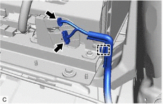
REMOVE HYBRID BATTERY HOSE ASSEMBLY
-
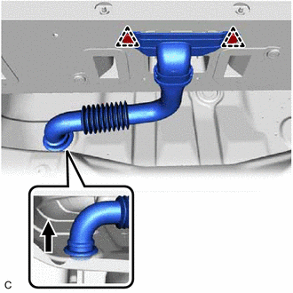
Disconnect the hybrid battery hose assembly from the vehicle.
-
Remove the 2 clips and hybrid battery hose assembly from the HV battery.
-
-
REMOVE NO. 1 HYBRID BATTERY INTAKE DUCT (for RH Side)
-
REMOVE NO. 2 HYBRID BATTERY INTAKE DUCT (for RH Side)
-
REMOVE CENTER REAR SEATBACK HINGE SUB-ASSEMBLY
-
REMOVE NO. 1 HV BATTERY SHIELD PANEL
CAUTION:
Wear insulated gloves.
-
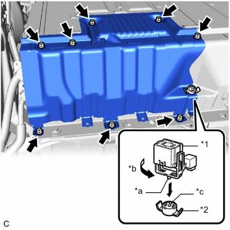
*1 Service Plug Grip *2 Battery Cover Lock Striker *a Projection *b Turn *c Button Using the service plug grip, remove the battery cover lock striker.
Tech Tips
Insert the projection of the service plug grip and turn the button of the battery cover lock striker counterclockwise to release the lock.
-
Remove the 8 nuts and No. 1 HV battery shield panel from the HV battery.
-
-
REMOVE NO. 3 HV BATTERY SHIELD PANEL
CAUTION:
Wear insulated gloves.
-
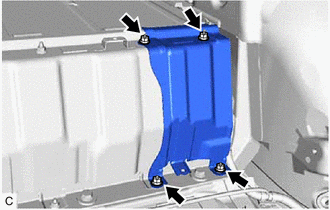
Remove the 4 nuts and No. 3 HV battery shield panel from the HV battery.
-
-
REMOVE NO. 2 HV BATTERY SHIELD PANEL
CAUTION:
Wear insulated gloves.
-
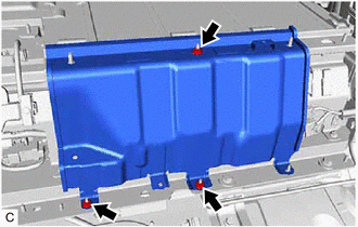
Remove the 3 nuts and No. 2 HV battery shield panel from the HV battery.
-
-
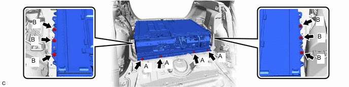
DISCONNECT WIRE HARNESS
CAUTION:
Wear insulated gloves.
Note
Insulate each disconnected high-voltage connector with insulating tape. Wrap the connector from the wire harness side to the end of the connector.
-
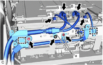
*a Earth Terminal Disconnect the 2 HV battery junction block assembly connectors (A).
-
Disconnect the 2 HV battery junction block assembly connectors (B).
-
Remove the 2 nuts and disconnect the earth terminals.
-
Remove the nut.
-
Disengage the 3 clamps.
-
-
DISCONNECT FLOOR WIRE
CAUTION:
Wear insulated gloves.
-
Disengage the clamp.
-
Disconnect the 2 HV battery connectors.
-
-
REMOVE HV BATTERY
CAUTION:
Wear insulated gloves.
-
Remove the 4 bolts (A) and 6 bolts (B).
Note
Do not allow foreign matter, such as grease or oil, to adhere to the bolts of the HV battery.
-
Set the 4 hooks and 2 straps as shown in the illustration.
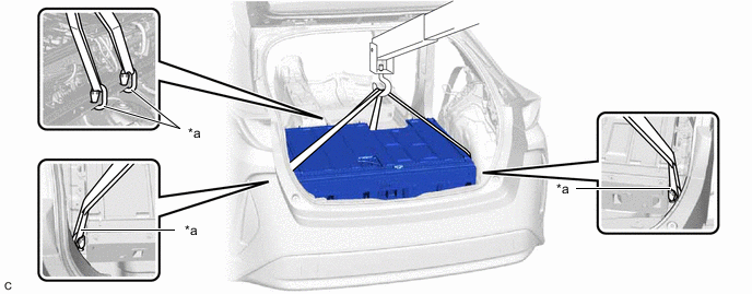
*a Hook - - -
Using a suitable adaptor such as straps, remove the HV battery while tilting it.
Note
-
To prevent the wire harness from being caught, make sure to bundle the wire harness using insulating tape or equivalent.
-
Use cardboard or another similar material to protect the HV battery and vehicle body from damage.
-
Since the HV battery is very heavy, 2 people are needed to remove it. When removing the HV battery, be careful not to damage the parts around it.
-
When removing the HV battery from the vehicle, do not allow it to contact the vehicle.
-
When removing/installing/moving the HV battery, make sure not to tilt it more than 80°.
-
Insulate the disconnected terminals or connectors with insulating tape.
-
If the HV battery has been struck or dropped, replace it.
-
When removing the HV battery, make sure to cover the opening on the front of the HV battery with a piece of cloth.
-
-
-
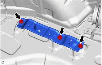
REMOVE NO. 4 HV BATTERY MOUNT BRACKET
Tech Tips
Perform this procedure only when replacement of the No. 4 HV battery mount bracket is necessary.
-
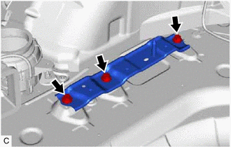
Remove the 3 bolts and No. 4 HV battery mount bracket.
-
-
REMOVE NO. 3 HV BATTERY MOUNT BRACKET
Tech Tips
Perform this procedure only when replacement of the No. 3 HV battery mount bracket is necessary.
-
Remove the 3 bolts and No. 3 HV battery mount bracket.
-
-
REMOVE NO. 2 HV BATTERY MOUNT BRACKET
Tech Tips
Perform this procedure only when replacement of the No. 2 HV battery mount bracket is necessary.
-
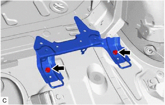
Remove the 2 bolts and No. 2 HV battery mount bracket.
-
-
REMOVE NO. 1 HV BATTERY MOUNT BRACKET
Tech Tips
Perform this procedure only when replacement of the No. 1 HV battery mount bracket is necessary.
-
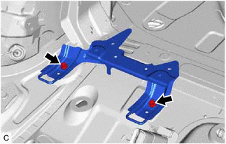
Remove the 2 bolts and No. 1 HV battery mount bracket.
-
-
PERFORM RECOVERY INSPECTION
-
Before returning the HV battery, make sure to perform a recovery inspection.
-