BATTERY ECU REMOVAL
CAUTION / NOTICE / HINT
The necessary procedures (adjustment, calibration, initialization, or registration) that must be performed after parts are removed and installed, or replaced during battery ECU assembly removal/installation are shown below.
| Replaced Part or Performed Procedure | Necessary Procedures | Effect/Inoperative Function when Necessary Procedure not Performed | Link |
|---|---|---|---|
| Auxiliary battery terminal is disconnected/reconnected | Memorize steering angle neutral point | Lane departure alert system (w/ Steering Control) | |
| Intelligent clearance sonar system*1 | |||
| Simple intelligent parking assist system*1 | |||
| Pre-crash safety system | |||
| Adaptive high beam system | |||
| Parking assist monitor system | |||
| Initialize back door lock | Power door lock control system | ||
| Replacement of battery ECU assembly | Current sensor offset learning | DTCs are stored |
Click here Click here
CAUTION:
-
Orange wire harnesses and connectors indicate high-voltage circuits. To prevent electric shock, always follow the procedure described in the repair manual.
-

To prevent electric shock, wear insulated gloves when working on wire harnesses and components of the high voltage system.
Note
-
If the wrong type of battery ECU assembly is installed, the power switch cannot be turned on (READY).
-
After installing the battery ECU assembly, perform the following to check that the power switch can be turned on (READY).
-
Turn the power switch on (READY).
-
Turn the power switch off and wait for 30 seconds or more.
-
Turn the power switch on (READY) again.
PROCEDURE
-
PRECAUTION
Note
After turning the power switch off, waiting time may be required before disconnecting the cable from the negative (-) auxiliary battery terminal. Therefore, make sure to read the disconnecting the cable from the negative (-) auxiliary battery terminal notices before proceeding with work.
-
WHEN REPLACING BATTERY ECU ASSEMBLY
HV battery learning values are stored in the battery ECU assembly and ECM and are used to detect malfunctions and illuminate the hybrid battery indicator light in the combination meter assembly. When either of these ECUs is replaced, the new ECU receives the HV battery learning values from the other ECU and stores them.
Note
-
Do not replace the battery ECU assembly and ECM at the same time as the HV battery learning values will be lost. However, if it is necessary to replace both ECUs at the same time, replace them by following the procedure below.
-
Do not replace the battery ECU assembly or ECM with a used one from another vehicle.
-
Procedure when replacing both battery ECU assembly and ECM:
-
Disconnect the cable from the negative (-) auxiliary battery terminal.
-
Replace either ECU.
-
Connect the cable to the negative (-) auxiliary battery terminal.
-
Turn the power switch on (READY) and wait for 5 minutes or more.
-
Turn the power switch off and disconnect the cable from the negative (-) auxiliary battery terminal.
-
Replace the other ECU.
-
Connect the cable to the negative (-) auxiliary battery terminal.
-
Check that the power switch can be turned on (READY).
Tech Tips
If the battery ECU assembly and ECM are replaced at the same time without following the above procedure, replace either of the ECUs with its original one and then replace it again by following the above procedure. If the correct procedure is not followed, perform the procedure again from the beginning.
-
-
-
REMOVE UPPER HYBRID BATTERY COVER SUB-ASSEMBLY
-
REMOVE BATTERY ECU ASSEMBLY
CAUTION:
Be sure to wear insulated gloves and protective goggles.
Note
Insulate the disconnected high-voltage connector with insulating tape.
-
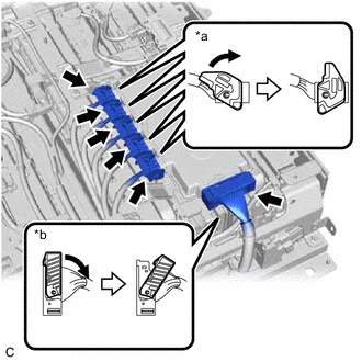
*a Lock Lever (A) *b Lock Lever (B) Release each lock, move each lock lever (A) as shown in the illustration, and then disconnect the 5 battery ECU assembly connectors.
-
Release the lock, move the lock lever (B) as shown in the illustration, and then disconnect the battery ECU assembly connector.
-
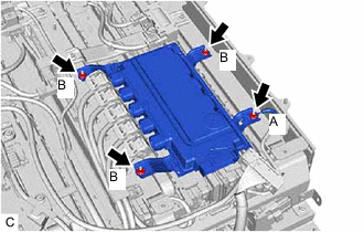
Remove the nut (A) and disconnect the wire harness.
-
Remove the 3 nuts (B) and battery ECU assembly from the HV battery.
Note
If the battery ECU assembly has been struck or dropped, replace it.
-