REAR CRANKSHAFT OIL SEAL INSTALLATION

PROCEDURE
-
INSTALL REAR ENGINE OIL SEAL
-
Using height adjustment attachments and plate lift attachments, place the engine assembly on a flat level surface.
Note
-
Using height adjustment attachments and plate lift attachments, keep the engine assembly horizontal.
-
To prevent the oil pan sub-assembly from deforming, do not place any attachments under the oil pan sub-assembly of the engine assembly.
-
Using an engine sling device and engine lift, secure the engine assembly before servicing.
-
-
Apply MP grease to the lip of a new rear engine oil seal.
Note
Keep the lip free from foreign matter.
-
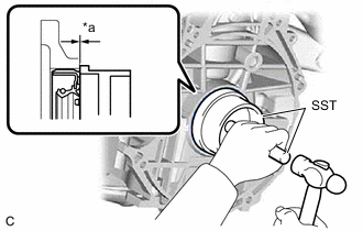
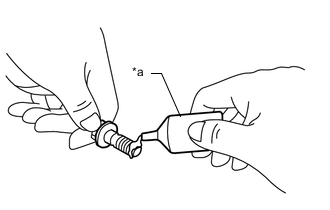
*a Tap in Depth Using SST and a hammer, tap in the rear engine oil seal.
- SST
- 09223-15030
- 09950-70010 ( 09951-07100 )
Rear Engine Oil Seal Tap in Depth -1.0 to 1.0 mm (-0.0394 to 0.0394 in.) Note
-
Keep the lip free from foreign matter.
-
Do not tap in the rear engine oil seal at an angle.
-
-
INSTALL ONE-WAY CLUTCH HOLDING PLATE
-
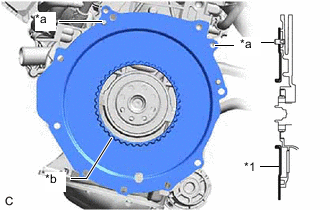
*1 One-way Clutch Holding Plate *a Knock Pin *b Spline Align the one-way clutch holding plate with the knock pins and install it.
-
Apply genuine clutch spline grease to the splines of the one-way clutch holding plate.
Grease Toyota Genuine Clutch Spline Grease or equivalent
-
-
INSTALL ONE-WAY CLUTCH ASSEMBLY
-
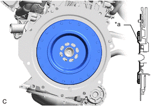
*a Spline Align the one-way clutch assembly with the splines of the one-way clutch holding plate and install it.
-
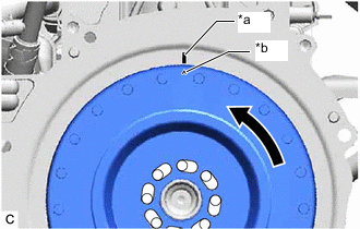
*a One-way Clutch Holding Plate Mark *b One-way Clutch Assembly Mark Rotate the one-way clutch assembly counterclockwise until the timing mark of the one-way clutch holding plate and one-way clutch assembly are close and the bolt holes are aligned.
Tech Tips
As shown in the illustration, it is not required to perfectly align the bolt holes.
-
-
INSTALL FLYWHEEL SUB-ASSEMBLY
-
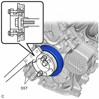
Using SST, hold the crankshaft pulley.
- SST
- 09213-58014 ( 91551-80840 )
- 09330-00021
-
Clean the 8 bolts and 8 bolt holes.
-
*a Adhesive Apply adhesive to 2 or 3 threads at the end of each of the 8 bolts.
Adhesive Toyota Genuine Adhesive 1324, Three Bond 1324 or equivalent -
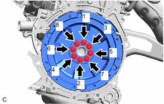
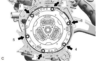
Install and uniformly tighten the 8 bolts in several steps in the order shown in the illustration.
- Torque:
- 49 N*m { 500 kgf*cm, 36 ft.*lbf }
Note
Do not start the engine for at least 1 hour after installing the flywheel sub-assembly.
-
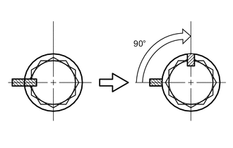

Paint Mark Mark each bolt head with paint as shown in the illustration.
-
Tighten the 8 bolts by 90° in the same order.
-
Check that the paint marks are now at a 90° angle.
-
Check that the crankshaft turns smoothly.
-
-
INSTALL TRANSMISSION INPUT DAMPER ASSEMBLY
-
Using SST, hold the crankshaft pulley.
- SST
- 09213-58014 ( 91551-80840 )
- 09330-00021
-
Install the transmission input damper assembly to the flywheel sub-assembly with the 6 bolts. Uniformly tighten the 6 bolts in the order shown in the illustration.
- Torque:
- 30 N*m { 306 kgf*cm, 22 ft.*lbf }
Note
-
Make sure that there is no oil on the transmission input damper assembly or flywheel sub-assembly.
-
Make sure to install the transmission input damper assembly in the correct direction.
-
Do not allow grease to contact the splines of the transmission input damper assembly or the input shaft.
-
-
INSTALL ENGINE ASSEMBLY