CAMSHAFT INSTALLATION

PROCEDURE
-
INSTALL NO. 1 CAMSHAFT BEARING
-
INSTALL NO. 2 CAMSHAFT BEARING
-
INSTALL CAMSHAFT TIMING GEAR ASSEMBLY
Tech Tips
Perform "Inspection After Repair" after replacing the camshaft timing gear assembly.
-
w/ Canister Pump Mode:
-
w/o Canister Pump Mode:
-
Secure the hexagonal portion of the camshaft in a soft jaw vise.
-
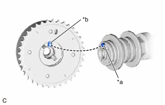
*a Knock Pin *b Knock Pin Hole Align and fit the knock pin of the camshaft to the knock pin hole of the camshaft timing gear assembly.
-
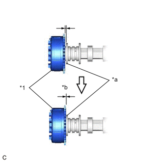
*1 Camshaft Timing Gear Assembly *a Camshaft Flange *b No Gap Check that there is no gap between the camshaft timing gear assembly and camshaft flange.
-
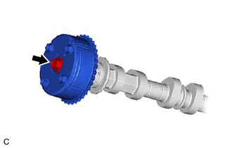
Tighten the bolt with the camshaft timing gear assembly secured in place.
- Torque:
- 54 N*m { 551 kgf*cm, 40 ft.*lbf }
Note
When tightening the bolt, do not allow the camshaft timing gear assembly to rotate.
-
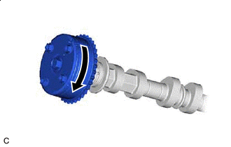

Lock Check that the camshaft timing gear assembly can move in the retard direction (clockwise) and locks in the most retarded position.
-
-
SET NO. 1 VALVE ROCKER ARM SUB-ASSEMBLY
-
INSTALL CAMSHAFT
Tech Tips
Perform "Inspection After Repair" after replacing the camshaft.
-
w/ Canister Pump Mode:
-
w/o Canister Pump Mode:
-
Clean the camshaft journals.
-
Apply a light coat of engine oil to the camshaft journals, camshaft housing sub-assembly and camshaft bearing caps.
-
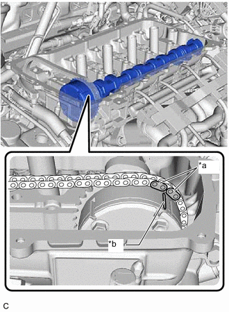
*a Paint Mark *b Timing Mark Hold up the chain sub-assembly, align the timing mark with the paint mark and install the camshaft.
-
-
INSTALL NO. 2 CAMSHAFT
Tech Tips
Perform "Inspection After Repair" after replacing the No. 2 camshaft.
-
w/ Canister Pump Mode:
-
w/o Canister Pump Mode:
-
Clean the No. 2 camshaft journals.
-
Apply a light coat of engine oil to the No. 2 camshaft journals, camshaft housing sub-assembly and camshaft bearing caps.
-
Install the No. 2 camshaft to the camshaft housing sub-assembly.
-
-
INSTALL CAMSHAFT BEARING CAP
-
Check the marks and numbers on the camshaft bearing caps, and then remove the service bolts and spacers in the order shown in the illustration. Immediately after removing the service bolts and spacers for 1 camshaft bearing cap, install the camshaft bearing cap with the bolts in the order shown in the illustration.
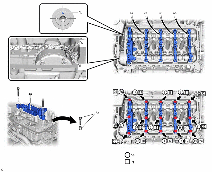
*a Service bolt and spacer (Used to temporarily secure the camshaft housing sub-assembly) *b Knock Pin *c Paint Mark *d Timing Mark *e The removal order of the service bolts and spacers for temporarily tightening the camshaft housing sub-assembly *f The installation order of the parts - Torque:
- 27 N*m { 275 kgf*cm, 20 ft.*lbf }
Note
If the bolts are loosened all at once, FIPG on the camshaft housing sub-assembly and cylinder head sub-assembly may separate, resulting in oil leaks. Therefore, be sure to remove the service bolts and spacers from one camshaft bearing cap at a time.
Tech Tips
Make sure that the orientation of the knock pin and timing mark of the camshaft are as shown in the illustration.
-
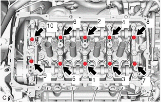
Tighten the 10 bolts in the order shown in the illustration.
- Torque:
- 16 N*m { 163 kgf*cm, 12 ft.*lbf }
-
Check the torque of each bolt again.
-
-
INSTALL CAMSHAFT TIMING SPROCKET
-
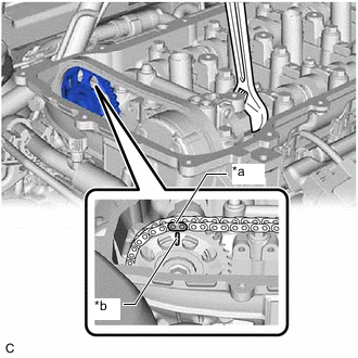
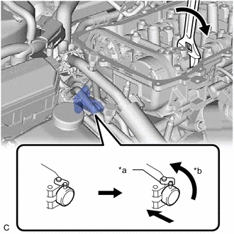
*a Paint Mark *b Timing Mark Hold the hexagonal portion of the camshaft with a wrench and turn the camshaft slightly counterclockwise to release the chain sub-assembly.
Note
Do not turn the camshaft more than necessary.
-
Align the paint mark with the timing mark to install the chain sub-assembly.
-
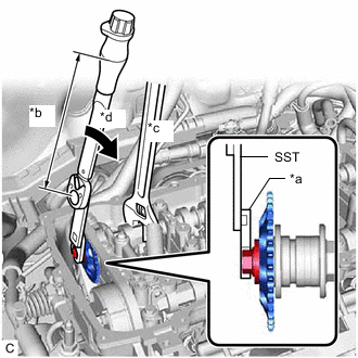
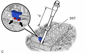
*a 14 mm Union Nut Wrench *b Torque Wrench Fulcrum Length *c Hold *d Turn Using SST, a 14 mm union nut wrench and a wrench, hold the hexagonal portion of the No. 2 camshaft and install the camshaft timing sprocket to the No. 2 camshaft with the bolt.
- SST
- 09961-00950
Torque Specified tightening torque 54 N*m (551 kgf*cm, 40 ft.*lbf) Note
-
Make sure to securely hold the No. 2 camshaft.
-
As the crankshaft cannot be rotated counterclockwise due to the one-way clutch assembly, if the camshaft timing gear assembly rotates to the point that the timing mark cannot be seen, it will not be possible to adjust the valve timing with the engine installed to the vehicle.
Tech Tips
-
Calculate the torque wrench reading when changing the fulcrum length of the torque wrench.
-
When using a 14 mm union nut wrench (fulcrum length of 25 mm (0.984 in.)) + SST (fulcrum length of 150 mm (5.91 in.)) + torque wrench (fulcrum length of 255 mm (10.0 in.)): 32 N*m (326 kgf*cm, 24 ft.*lbf)
-
-
INSTALL NO. 1 CHAIN TENSIONER ASSEMBLY
-
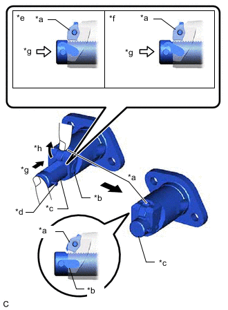
*a Cam *b Hook *c Plunger *d Pin *e Correct *f Incorrect *g Push *h Raise Raise the cam, then fully push in the plunger and engage the hook with the pin so that the plunger is in the position shown in the illustration.
Note
Make sure that the cam engages with the first tooth of the plunger to allow the hook to pass over the pin.
-
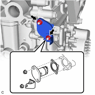
Install a new gasket, the bracket and No. 1 chain tensioner assembly to the timing chain cover sub-assembly with the 2 nuts.
- Torque:
- 12 N*m { 122 kgf*cm, 9 ft.*lbf }
Note
If the hook releases the plunger while the No. 1 chain tensioner assembly is being installed, set the hook again.
-
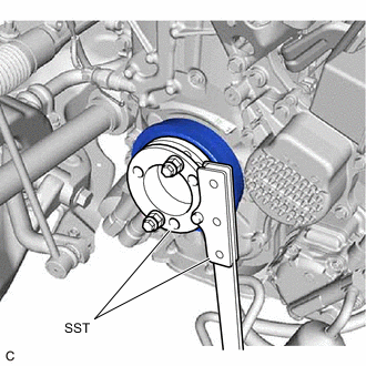
Using SST, hold the crankshaft pulley.
- SST
- 09213-58014 ( 91551-80840 )
- 09330-00021
Note
-
Make sure to securely hold the crankshaft.
-
The crankshaft cannot be rotated counterclockwise due to the one-way clutch assembly. When releasing the hook of the No. 1 chain tensioner assembly, if the timing marks and paint marks become misaligned to the point where they cannot be seen due to the crankshaft being rotated, it will not be possible to adjust the valve timing with the engine installed to the vehicle.
-
*a Hook *b Release Using a wrench, rotate the camshaft clockwise slightly and check that the hook is released.
-
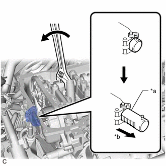
*a Plunger *b Plunger is extended Using a wrench, turn the camshaft counterclockwise and check that the plunger is extended.
Tech Tips
Make sure that a click sound is heard to confirm that the plunger has extended.
-
Remove SST.
-
-
INSTALL NO. 2 CHAIN VIBRATION DAMPER
-
*a Torque Wrench Fulcrum Length Using SST, install the No. 2 chain vibration damper to the No. 1 camshaft bearing cap with the 2 bolts.
- SST
- 09961-00950
Torque Specified tightening torque 10 N*m (102 kgf*cm, 7 ft.*lbf) Tech Tips
-
Calculate the torque wrench reading when changing the fulcrum length of the torque wrench.
-
When using SST ((fulcrum length of 150 mm (5.91 in.)) + torque wrench (fulcrum length of 162 mm (6.38 in.)): 5.2 N*m (53 kgf*cm, 46 in.*lbf)
-
-
SET NO. 1 CYLINDER TO TDC (COMPRESSION)
-
INSTALL SPARK PLUG TUBE GASKET
-
INSTALL CYLINDER HEAD COVER GASKET
-
INSTALL CYLINDER HEAD COVER SUB-ASSEMBLY
-
INSTALL FUEL VAPOR FEED PIPE
-
INSTALL PURGE VALVE (PURGE VSV)
-
CONNECT NO. 9 WATER BY-PASS HOSE
-
CONNECT NO. 8 WATER BY-PASS HOSE
-
INSTALL EGR PIPE ASSEMBLY
-
CONNECT NO. 1 FUEL VAPOR FEED HOSE
-
CONNECT ENGINE WIRE
-
Connect the engine wire to the cylinder head cover sub-assembly with the bolt.
- Torque:
- 8.0 N*m { 82 kgf*cm, 71 in.*lbf }
-
Engage the 4 clamps.
-
Connect the 4 connectors.
-
-
INSTALL IGNITION COIL ASSEMBLY
-
CONNECT NO. 2 VENTILATION HOSE
-
INSTALL NO. 1 ENGINE COVER SUB-ASSEMBLY
-
INSTALL OUTER COWL TOP PANEL SUB-ASSEMBLY
-
ADD ENGINE COOLANT (for Engine)
-
INSPECT FOR COOLANT LEAK (for Engine)
-
INSTALL NO. 1 ENGINE UNDER COVER ASSEMBLY