ENGINE ASSEMBLY REMOVAL
CAUTION / NOTICE / HINT
The necessary procedures (adjustment, calibration, initialization, or registration) that must be performed after parts are removed and installed, or replaced during engine assembly removal/installation are shown below.
| Replaced Part or Performed Procedure | Necessary Procedure | Effect/Inoperative Function when Necessary Procedure not Performed | Link |
|---|---|---|---|
| Auxiliary battery terminal is disconnected/reconnected | Memorize steering angle neutral point | Lane departure alert system (w/ Steering Control) | |
| Intelligent clearance sonar system*1 | |||
| Simple advanced parking guidance system*1 | |||
| Pre-collision system | |||
| Adaptive high beam system | |||
| Parking assist monitor system | |||
| Initialize back door lock | Power door lock control system | ||
| Replacement of inverter with converter assembly | Resolver learning |
|
|
| Replacement of ECM | Perform Vehicle Identification Number (VIN) registration (w/ Canister Pump Module) | MIL comes on | |
| Perform Vehicle Identification Number (VIN) or frame number registration (w/o Canister Pump Module) | |||
for SFI system (w/ Canister Pump Module) |
Inspection After Repair |
|
|
for SFI system (w/o Canister Pump Module) |
Inspection After Repair |
|
|
| Suspension, tires, etc. (The vehicle height changes because of suspension or tire replacement) |
|
|
|
| Rear television camera assembly optical axis (Back camera position setting) | Parking assist monitor system | ||
| Initialize No. 1 headlight ECU sub-assembly LH |
|
||
| Front wheel alignment adjustment |
|
|
|
| Replacement of hybrid vehicle transaxle assembly |
|
|
*1: When performing learning using the GTS.
*2: w/ Adaptive High Beam System
CAUTION:
-
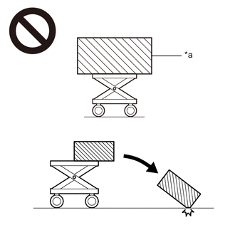
*a An Object Exceeding Weight Limit of Engine Lifter The engine assembly with transaxle is very heavy. Be sure to follow the procedure described in the repair manual, or the engine lifter may suddenly drop or the engine assembly with transaxle may fall off the engine lifter.
-
To prevent burns, do not touch the engine, exhaust manifold or other high temperature components while the engine is hot.
PROCEDURE
-
PRECAUTION
CAUTION:
The vehicle has a hybrid system that operates at voltages up to 650 V. The hybrid system uses an HV battery that contains an electrolyte which is a strong alkali solution that includes potassium hydroxide. Be sure to follow the instructions in this manual to handle the system correctly. Failure to do so may result in serious injury or electrocution.
Note
After turning the power switch off, waiting time may be required before disconnecting the cable from the negative (-) auxiliary battery terminal. Therefore, make sure to read the disconnecting the cable from the negative (-) auxiliary battery terminal notices before proceeding with work.
-
DISCHARGE FUEL SYSTEM PRESSURE
-
ALIGN FRONT WHEELS FACING STRAIGHT AHEAD
-
SECURE STEERING WHEEL
-
REMOVE FRONT WHEELS
-
REMOVE NO. 1 ENGINE UNDER COVER ASSEMBLY
-
Remove the 10 clips, 4 bolts and No. 1 engine under cover assembly.
-
-
REMOVE REAR ENGINE UNDER COVER LH
-
except Rough Road Area Specification Vehicles:
-
Remove the 4 clips, screw and rear engine under cover LH.
-
-
for Rough Road Area Specification Vehicles:
-
Remove the 5 clips, screw and rear engine under cover LH.
-
-
-
REMOVE REAR ENGINE UNDER COVER RH
-
except Rough Road Area Specification Vehicles:
-
Remove the 4 clips, screw and rear engine under cover RH.
-
-
for Rough Road Area Specification Vehicles:
-
Remove the 5 clips, screw and rear engine under cover RH.
-
-
-
REMOVE NO. 2 ENGINE UNDER COVER
-
Remove the 3 bolts and No. 2 engine under cover.
-
-
DRAIN ENGINE OIL
-
DRAIN ENGINE COOLANT (for Engine)
-
DRAIN HYBRID TRANSAXLE FLUID
-
REMOVE NO. 1 ENGINE COVER SUB-ASSEMBLY
-
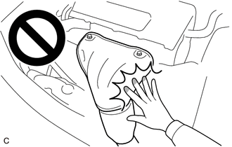
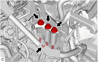
Disengage the 3 clips in the order shown in the illustration to remove the No. 1 engine cover sub-assembly.
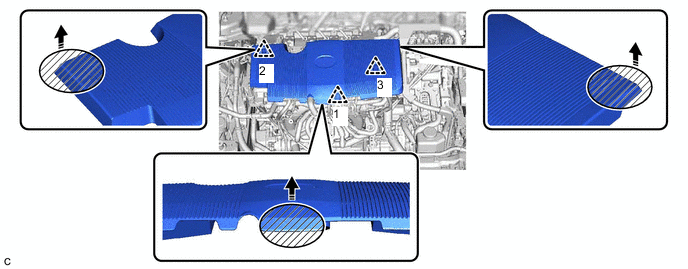

Areas to be Held when Lifting No. 1 Engine Cover Sub-assembly 
Remove in this Direction Note
-
Pull the No. 1 engine cover sub-assembly straight up to remove. Attempting to pull the No. 1 engine cover sub-assembly forward or attempting to pull it up by holding the left and right sides may cause the No. 1 engine cover sub-assembly to break.
-
If the clips are not disengaged in the order shown in the illustration, the No. 1 engine cover sub-assembly may be damaged.
-
-
-
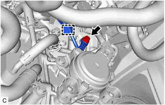
DISCONNECT NO. 8 WATER BY-PASS HOSE
-
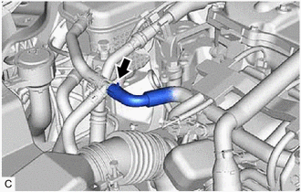
Slide the clip and disconnect the No. 8 water by-pass hose from the No. 2 water by-pass hose assembly.
-
-
REMOVE RADIATOR SUPPORT OPENING COVER
-
REMOVE INLET NO. 2 AIR CLEANER
-
REMOVE THROTTLE BODY ASSEMBLY
-
REMOVE AIR CLEANER FILTER ELEMENT SUB-ASSEMBLY
-
REMOVE AIR CLEANER CASE SUB-ASSEMBLY
-
REMOVE AIR CLEANER BRACKET
-
REMOVE INLET NO. 1 AIR CLEANER
-
REMOVE INVERTER WITH CONVERTER ASSEMBLY
-
DISCONNECT NO. 3 RADIATOR HOSE
-
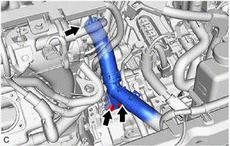
Remove the 2 bolts from the hybrid vehicle transaxle assembly.
-
Slide the clip and disconnect the No. 3 radiator hose from the water outlet.
-
-
DISCONNECT NO. 2 RADIATOR HOSE
-
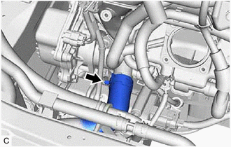
Slide the clip and disconnect the No. 2 radiator hose from the water inlet sub-assembly.
-
-
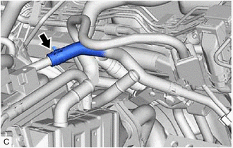
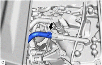
DISCONNECT OUTLET HEATER WATER HOSE E
-
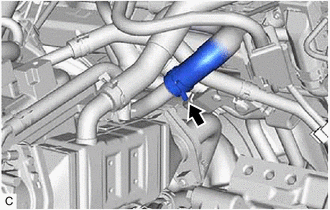
Slide the clip and disconnect the outlet heater water hose E from the No. 1 water by-pass pipe.
-
-
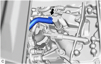
DISCONNECT INLET HEATER WATER HOSE A
-
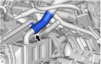
Slide the clip and disconnect the inlet heater water hose A from the EGR valve assembly.
-
-
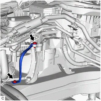
DISCONNECT NO. 1 FUEL VAPOR FEED HOSE
-
Slide the clip and disconnect the No. 1 fuel vapor feed hose from the fuel vapor feed pipe.
-
-
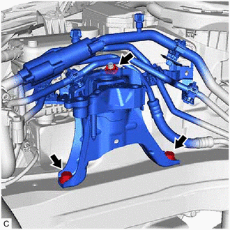
DISCONNECT FUEL TUBE SUB-ASSEMBLY
-
DISCONNECT INLET HYBRID RADIATOR HOSE
-
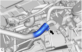
Slide the clip and disconnect the inlet hybrid radiator hose from the motor cooling cooler.
-
-
DISCONNECT OUTLET NO. 1 HYBRID WATER PUMP HOSE
-
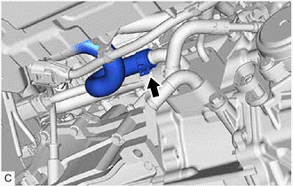
Slide the clip and disconnect the outlet No. 1 hybrid water pump hose from the motor cooling cooler.
-
-
SEPARATE COMPRESSOR WITH MOTOR ASSEMBLY
-
*a Bracket Remove the bolt and disconnect the bracket.
-
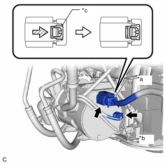
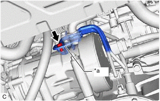
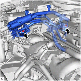
*a Connector (A) *b Connector (B) *c Green-colored Lock Using a screwdriver, slide the green-colored lock of the connector (A) as shown in the illustration to release it and disconnect the connector.
CAUTION:
Make sure to wear insulated gloves.
Note
Insulate the disconnected terminals and connector with insulating tape.
-
Disconnect the connector (B).
-
Type A:
-
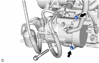
Remove the bolt and 2 nuts.
-
Using an E8 "TORX" socket wrench, remove the 2 stud bolts and compressor with motor assembly.
-
-
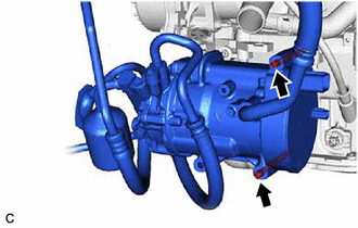
Type B:
-
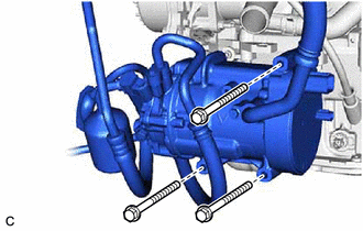
Remove the 3 bolts and separate the compressor with motor assembly.
-
-
-
DISCONNECT NO. 3 ENGINE WIRE
-
Disengage the clamp.
-
Remove the bolt and disconnect the No. 3 engine wire from the hybrid vehicle transaxle assembly.
-
-
REMOVE COLUMN HOLE COVER SILENCER SHEET
-
SEPARATE NO. 2 STEERING INTERMEDIATE SHAFT ASSEMBLY
-
SEPARATE NO. 1 STEERING COLUMN HOLE COVER SUB-ASSEMBLY
-
REMOVE FRONT FLOOR COVER LH
-
REMOVE FRONT FLOOR COVER RH
Tech Tips
Use the same procedure as for the LH side.
-
REMOVE FRONT CENTER FLOOR BRACE
-
REMOVE FRONT EXHAUST PIPE ASSEMBLY (TWC: Rear Catalyst)
-
DISCONNECT INLET NO. 1 OIL COOLER HOSE
-
Slide the clip and disconnect the inlet No. 1 oil cooler hose from the hybrid vehicle transaxle assembly.
-
-
DISCONNECT OUTLET NO. 1 OIL COOLER HOSE
-
Slide the clip and disconnect the outlet No. 1 oil cooler hose from the hybrid vehicle transaxle assembly.
-
-
REMOVE FRONT AXLE SHAFT NUT LH
-
REMOVE FRONT AXLE SHAFT NUT RH
Tech Tips
Use the same procedure as for the LH side.
-
SEPARATE FRONT SPEED SENSOR LH
-
SEPARATE FRONT SPEED SENSOR RH
Tech Tips
Use the same procedure as for the LH side.
-
SEPARATE TIE ROD END SUB-ASSEMBLY LH
-
SEPARATE TIE ROD END SUB-ASSEMBLY RH
Tech Tips
Use the same procedure as for the LH side.
-
SEPARATE FRONT STABILIZER LINK ASSEMBLY LH
-
SEPARATE FRONT STABILIZER LINK ASSEMBLY RH
Tech Tips
Use the same procedure as for the LH side.
-
SEPARATE FRONT LOWER NO. 1 SUSPENSION ARM SUB-ASSEMBLY LH
-
SEPARATE FRONT LOWER NO. 1 SUSPENSION ARM SUB-ASSEMBLY RH
Tech Tips
Use the same procedure as for the LH side.
-
SEPARATE FRONT DRIVE SHAFT ASSEMBLY LH
-
SEPARATE FRONT DRIVE SHAFT ASSEMBLY RH
Tech Tips
Use the same procedure as for the LH side.
-
REMOVE FRONT DRIVE SHAFT ASSEMBLY LH
-
REMOVE FRONT DRIVE SHAFT ASSEMBLY RH
Tech Tips
Use the same procedure as for the LH side.
-
REMOVE FRONT DRIVE SHAFT HOLE SNAP RING
-
REMOVE REAR SIDE RAIL REINFORCEMENT SUB-ASSEMBLY LH
-
REMOVE REAR SIDE RAIL REINFORCEMENT SUB-ASSEMBLY RH
Tech Tips
Use the same procedure as for the LH side.
-
REMOVE ENGINE ASSEMBLY WITH TRANSAXLE
-
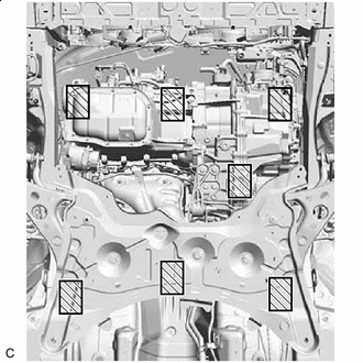
Attachment Installation Position Place height adjustment attachments and plate lift attachments in the positions shown in the illustration and set an engine lifter underneath the engine assembly with transaxle and front suspension crossmember sub-assembly.
Note
-
Using height adjustment attachments and plate lift attachments, keep the engine assembly with transaxle and front suspension crossmember sub-assembly level.
-
Do not perform any procedures while the engine assembly is suspended because doing so may cause the engine assembly to drop, resulting in injury. However, the engine assembly needs to be suspended when it is installed to or removed from an engine stand.
-
-
Remove the bolt and nut to disconnect the 2 cooler brackets.
-
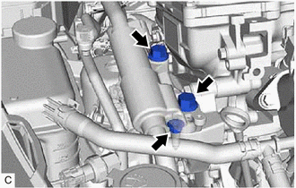
Remove the nut.
-
Remove the 2 bolts and separate the engine mounting insulator sub-assembly RH from the engine mounting bracket RH.
-
Remove the 3 bolts and nut to separate the engine mounting insulator LH from the hybrid vehicle transaxle assembly.
-
Remove the bolt and No. 2 engine mounting stay LH.
-
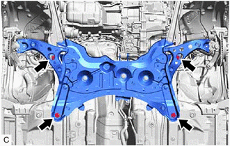
Remove the 4 bolts and separate the front suspension crossmember sub-assembly from the vehicle body.
-
Operate the engine lifter to remove the engine assembly with transaxle from the vehicle body.
Note
-
Make sure that the engine assembly with transaxle is clear of all wiring and hoses.
-
While lowering the engine assembly with transaxle from the vehicle, do not allow it to contact the vehicle body.
-
-
-
REMOVE WIRING HARNESS CLAMP BRACKET
-
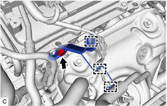
Disengage the 3 clamps.
-
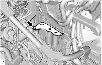
Remove the bolt and wiring harness clamp bracket from the cylinder head sub-assembly.
-
-
INSTALL ENGINE HANGERS
-
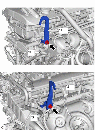
*1 No. 1 Engine Hanger *2 No. 2 Engine Hanger *3 Bolt Install the No. 1 engine hanger and No. 2 engine hanger with the 2 bolts.
- Torque:
- 43 N*m { 438 kgf*cm, 32 ft.*lbf }
Tech Tips
No. 1 Engine Hanger 12281-37021 No. 2 Engine Hanger 12282-37011 Bolt 91552-81050 -
Using an engine sling device and engine lifter, secure the engine assembly with transaxle.
Note
-
Adjust the angle of the sling device carefully to prevent damage or deformation to the engine hangers or engine assembly.
-
Do not perform any procedures while the engine assembly is suspended because doing so may cause the engine assembly to drop, resulting in injury. However, the engine assembly needs to be suspended when it is installed to or removed from an engine stand.
-
-
-
REMOVE ENGINE MOUNTING INSULATOR LH
Tech Tips
Perform this procedure only when replacement of the engine mounting insulator LH is necessary.
-
Remove the 4 bolts, nut and engine mounting insulator LH from the vehicle body.
-
-
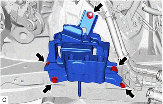
REMOVE ENGINE MOUNTING INSULATOR SUB-ASSEMBLY RH
Tech Tips
Perform this procedure only when replacement of the engine mounting insulator sub-assembly RH is necessary.
-
Remove the 2 bolts and No. 2 earth wire from the engine mounting insulator sub-assembly RH and vehicle body.
-
Remove the 2 bolts, nut and engine mounting insulator sub-assembly RH from the vehicle body.
-
-
REMOVE STARTER HOLE INSULATOR
-
REMOVE ENGINE WIRE
-
Remove the engine wire from the engine assembly with transaxle.
-
-
REMOVE ENGINE ASSEMBLY
-
REMOVE TRANSMISSION INPUT DAMPER ASSEMBLY
-
REMOVE FLYWHEEL SUB-ASSEMBLY
-
REMOVE ONE-WAY CLUTCH ASSEMBLY
-
REMOVE ONE-WAY CLUTCH HOLDING PLATE
-
INSTALL ENGINE ASSEMBLY TO ENGINE STAND
-
Install the engine assembly to an engine stand.
Note
-
Adjust the angle of the sling device carefully to prevent the engine assembly or engine hangers from deforming or becoming damaged.
-
Servicing an engine assembly while it is hanging is dangerous. This can be done only when installing/removing the engine assembly to/from an engine stand.
-
-
-
REMOVE ENGINE HANGERS
-
Remove the 2 bolts, No. 1 engine hanger and No. 2 engine hanger.
-