ELECTRIC VEHICLE CHARGER ASSEMBLY REMOVAL
CAUTION / NOTICE / HINT
The necessary procedures (adjustment, calibration, initialization, or registration) that must be performed after parts are removed and installed, or replaced during electric vehicle charger assembly removal/installation are shown below.
| Replaced Part or Performed Procedure | Necessary Procedures | Effect/Inoperative Function when Necessary Procedure not Performed | Link |
|---|---|---|---|
| Auxiliary battery terminal is disconnected/reconnected | Memorize steering angle neutral point | Lane departure alert system (w/ Steering Control) | |
| Intelligent clearance sonar system*1 | |||
| Simple intelligent parking assist system*1 | |||
| Pre-crash safety system | |||
| Adaptive high beam system | |||
| Parking assist monitor system | |||
| Initialize back door lock | Power door lock control system |
Click here Click here
CAUTION:
-
Orange wire harnesses and connectors indicate high-voltage circuits. To prevent electric shock, always follow the procedure described in the repair manual.
-

To prevent electric shock, wear insulated gloves when working on wire harnesses and components of the high voltage system.
PROCEDURE
-
PRECAUTION
Note
After turning the power switch off, waiting time may be required before disconnecting the cable from the negative (-) auxiliary battery terminal. Therefore, make sure to read the disconnecting the cable from the negative (-) auxiliary battery terminal notices before proceeding with work.
-
REMOVE SERVICE PLUG GRIP
-
REMOVE WINDSHIELD WIPER MOTOR AND LINK ASSEMBLY
-
REMOVE NO. 1 HEATER AIR DUCT SPLASH SHIELD SEAL (for LHD)
-
REMOVE NO. 2 HEATER AIR DUCT SPLASH SHIELD SEAL (for RHD)
-
REMOVE WATER GUARD PLATE
-
REMOVE COWL BODY MOUNTING REINFORCEMENT LH
-
REMOVE OUTER COWL TOP PANEL SUB-ASSEMBLY
-
REMOVE NO. 1 ENGINE COVER SUB-ASSEMBLY (w/o Canister Pump Module)
-
DISCONNECT ENGINE WIRE (w/o Canister Pump Module)
-
DISCONNECT ENGINE WIRE (w/ Canister Pump Module)
-
REMOVE CONNECTOR COVER ASSEMBLY
-
CHECK TERMINAL VOLTAGE
-
INSTALL CONNECTOR COVER ASSEMBLY
-
CONNECT ENGINE WIRE (w/ Canister Pump Module)
-
CONNECT ENGINE WIRE (w/o Canister Pump Module)
-
INSTALL NO. 1 ENGINE COVER SUB-ASSEMBLY (w/o Canister Pump Module)
-
INSTALL OUTER COWL TOP PANEL SUB-ASSEMBLY
-
INSTALL COWL BODY MOUNTING REINFORCEMENT LH
-
INSTALL WATER GUARD PLATE
-
INSTALL NO. 1 HEATER AIR DUCT SPLASH SHIELD SEAL (for LHD)
-
INSTALL NO. 2 HEATER AIR DUCT SPLASH SHIELD SEAL (for RHD)
-
INSTALL WINDSHIELD WIPER MOTOR AND LINK ASSEMBLY
-
REMOVE REAR SEAT CONSOLE BOX ASSEMBLY
-
REMOVE REAR SEAT CUSHION LEG SUB-ASSEMBLY
-
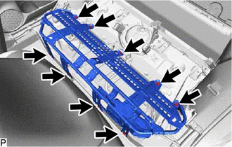
Remove the 9 bolts and rear seat cushion leg sub-assembly.
-
-
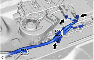
DISCONNECT HV BATTERY CHARGER WIRE
CAUTION:
Wear insulated gloves.
-
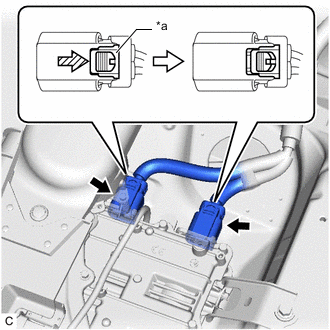
*a Green-colored Lock 
Slide Using a screwdriver, slide the green-colored lock of the connector as shown in the illustration to release it and disconnect the 2 electric vehicle charger assembly connectors.
-
w/ Solar Charging System:
-
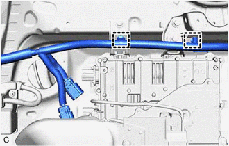
Disengage the 2 clamps.
-
-
-
REMOVE EV CHARGER DUCT
-
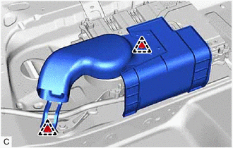
Remove the 2 clips and EV charger duct.
-
-
REMOVE NO. 2 INDOOR ELECTRICAL KEY ANTENNA ASSEMBLY
-
REMOVE ELECTRIC VEHICLE CHARGER ASSEMBLY
CAUTION:
Wear insulated gloves.
-
Disconnect the 3 connectors.
-
Disengage the 2 clamps.
-
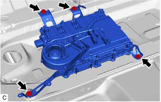
Remove the 4 bolts and electric vehicle charger assembly.
-
-
REMOVE CHARGER COOLING BLOWER
-
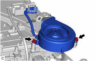
Disengage the clamp.
-
Remove the 2 bolts and charger cooling blower.
-