MOTOR GENERATOR CONTROL COMPUTER INSTALLATION

CAUTION / NOTICE / HINT
CAUTION:
To prevent foreign matter from entering the inverter with converter assembly, once the seal packing removal cover has been removed, work cannot be suspended until the motor generator control ECU kit is reinstalled.
Note
Do not cross-thread the bolts when installing them.
PROCEDURE
-
HOW TO PREVENT STATIC ELECTRICITY
- SST
- 09890-47010
Note
-
Static electricity should be eliminated when removing/installing the inverter with converter assembly.
-
Do not touch the electronic components of a circuit board.
-
Keep clothes away from electronic components.
-
Place the inverter with converter assembly and any removed electronic components on SST (antistatic mat).
-
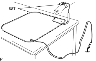
Wear an antistatic wrist strap.
-
Connect the ground clip of the antistatic mat securely to a ground point provided in the workshop or on a workbench (anchor bolt).
Tech Tips
If the ground clip cable is too short, use an extension cable.
-
Connect the ground clip of the antistatic wrist strap securely to the specified point of the antistatic mat.
-
When handling internal components of the inverter with converter assembly, use only antistatic gloves or bare hands to prevent damage from static electricity or the entry of foreign matter.
-
INSTALL MOTOR GENERATOR CONTROL ECU KIT
CAUTION:
To prevent foreign matter from entering the inverter with converter assembly, once the seal packing removal cover has been removed, work cannot be suspended until the motor generator control ECU kit is reinstalled.
Note
-
Do not touch the circuit board.
-
Do not allow any moisture to come into contact.
-
Do not lower the vibration dampening connectors until the motor generator control ECU kit is installed to the inverter with converter assembly.
-
Check that the 4 clips of the circuit board replacement jig are unlocked, and then while holding the sides of the circuit board, align the guide holes with the guide pins of the circuit board replacement jig and evenly set the circuit board on the circuit board replacement jig.
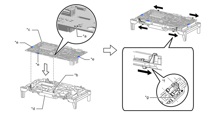
*a Guide Hole *b Guide Pin *c Circuit Board *d Circuit Board Replacement Jig *e Hold here *f Locked *g Locked Position - - 
Lock - - Note
Be careful not to touch any part of the circuit board other than the specified areas.
-
Lock the 4 clips to secure the circuit board replacement jig to the circuit board.
Note
When locking the clips of the circuit board replacement jig, do not apply excessive force to the clips, otherwise the circuit board replacement jig may be damaged.
Tech Tips
Make sure that the clips of the circuit board replacement jig are securely locked.
-
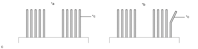
Check that the vibration dampening connectors are released.
-
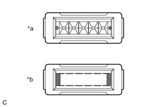
*a Guides Visible *b Guides Not Visible Check that the guides of each vibration dampening connector are visible as shown in the illustration.
Note
When the vibration dampening connectors are connected, the guides will no longer be visible and cannot be returned. Therefore, it any of the guides are not visible, replace the motor generator control computer kit with a new one.
Tech Tips
The guide on the back of each vibration dampening connector is a mechanism which guides the terminals so they do not bend when installing the circuit board.
-
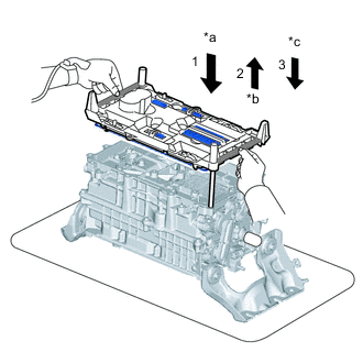
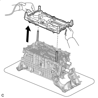
*a Align and lower circuit board replacement jig and circuit board *b Check terminals *c Set circuit board replacement jig and circuit board on sealing surface 
Rib While holding the circuit board replacement jig by the ribs, align the circuit board replacement jig and circuit board with the guide pins and lower them evenly onto inverter with converter assembly, checking that the terminals connect appropriately.
-
Evenly lift the circuit board replacement jig and circuit board to the top of the guide pins and check the terminals.
Tech Tips
Be careful not to remove the circuit board replacement jig and circuit board from the guide pins.
-
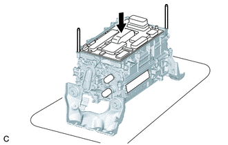
After confirming that the terminals are not bent or damaged, lower the circuit board replacement jig and circuit board evenly along the guide pins and set them on the inverter with converter assembly.
*a Correct *b Incorrect *c Terminal - - Tech Tips
Make sure that the circuit board replacement jig is evenly and completely contacting the sealing surface of the inverter with converter assembly.
Note
-
Do not touch the terminals.
-
If any of the terminals are bent, replace the inverter with converter assembly with a new one. Do not attempt to repair the terminals.
-
-
Unlock Unlock the 4 circuit board replacement jig clips as shown in the illustration.
Tech Tips
-
Make sure that all of the circuit board replacement jig clips are completely unlocked.
-
Be careful not to lift the circuit board replacement jig.
-
-
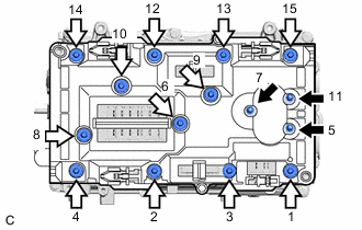
Bolt (A) 
Bolt (B) Temporarily install 15 new bolts evenly in several steps in the order shown in the illustration, and then tighten them to the specified torque.
- Torque:
- Bolt (A)
- 2.5 N*m { 25 kgf*cm, 22 in.*lbf }
- Bolt (B)
- 3.4 N*m { 35 kgf*cm, 30 in.*lbf }
-
Check the torque of the 15 bolts in the order shown in the illustration.
- Torque:
- Bolt (A)
- 2.5 N*m { 25 kgf*cm, 22 in.*lbf }
- Bolt (B)
- 3.4 N*m { 35 kgf*cm, 30 in.*lbf }
Note
Make sure that the bolts are securely contacting the circuit board.
-
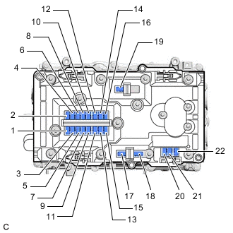
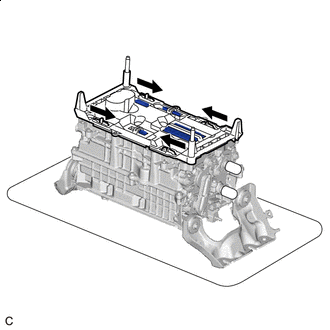
Push the 22 vibration dampening connectors to connect them in the order shown in the illustration.
Tech Tips
-
Push the center of each vibration dampening connector to connect them.
-
Make sure the vibration dampening connectors are connected securely by listening for a click sound and checking that they are level with the circuit board replacement jig.
-
-
Visually check that the vibration dampening connectors are securely connected.
Tech Tips
The vibration dampening connectors can be determined to be connected if they are level with the circuit board replacement jig.
-
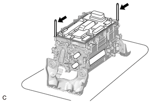
Rib While holding the circuit board replacement jig by the ribs, evenly lift the circuit board replacement jig straight up and remove it.
Tech Tips
Make sure that the circuit board replacement jig clips are released before removing the circuit board replacement jig.
-
Confirm that the following conditions are met before continuing work:
-
All of the vibration dampening connectors are securely connected.
-
All of the screws are installed and tightened to the specified torque.
-
The circuit board is free of foreign matter.
-
The circuit board is not damaged.
-
-
Clean the seal packing removal cover.
Note
Completely remove any seal packing and foreign matter from the seal packing removal cover using compressed air or a vacuum cleaner.
-
Install the seal packing removal cover to the inverter with converter assembly.
-
Remove the 2 guide pins by hand.
-
-
INSTALL INVERTER UPPER COVER
Note
-
Do not touch the circuit board.
-
Do not allow any moisture to come into contact.
-
Do not touch or allow grease or oil to contact the sealing surfaces of the inverter with converter assembly.
-
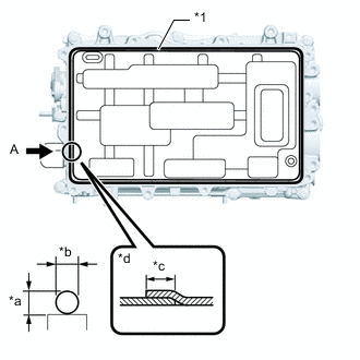
*1 Seal Packing *a 3.0 mm (0.118 in.) *b 3.0 mm (0.118 in.) *c Approximately 20 mm *d View A Starting from point A and moving clockwise, apply seal packing (diameter: 3.0 mm (0.118 in.)) in a continuous line as shown in the illustration.
Seal Packing Toyota Genuine Seal Packing 1207F Note
-
Install the inverter upper cover with in 3 minutes of applying seal packing.
-
Tighten the bolts within 15 minutes of applying seal packing.
-
-
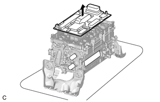
Remove the seal packing removal cover.
Note
Slowly remove the seal packing removal cover without touching the seal packing surface.
-
Using the low voltage connectors of the motor generator control ECU kit as a reference, temporarily install a new inverter upper cover.
Note
-
Make sure that the inverter upper cover is free of foreign matter.
-
Make sure to only press on area of the inverter upper cover shown in the illustration.
-
Make sure that the flanges of the inverter upper cover do not get caught on the inverter with converter assembly.
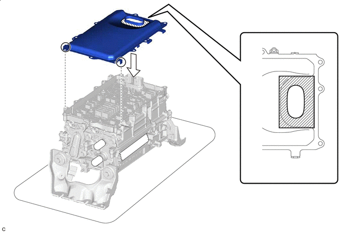

Area to Push - - -
-
Cover the low voltage connectors of the motor generator control ECU kit with masking tape.
-
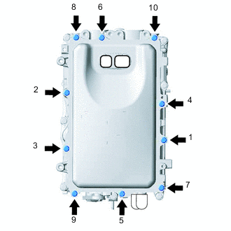
Temporarily install the 10 bolts evenly in several steps in the order shown in the illustration, and then tighten them to the specified torque.
- Torque:
- 8.4 N*m { 86 kgf*cm, 74 in.*lbf }
-
Check the torque of the 10 bolts in the order shown in the illustration.
- Torque:
- 8.4 N*m { 86 kgf*cm, 74 in.*lbf }
Note
Make sure that the bolts are securely contacting the inverter upper cover.
-
-
INSTALL WIRE HARNESS CLAMP BRACKET (w/o Canister Pump Module)
-
INSTALL WIRE HARNESS CLAMP BRACKET (w/ Canister Pump Module)
-
INSTALL INVERTER WITH CONVERTER ASSEMBLY
-
OPERATION CHECK
Tech Tips
After the repair, perform the operation checks as follows. Then check for DTCs again.
-
Operation check 1
-
Connect the GTS to the DLC3.
-
Turn the power switch on (IG), turn the GTS on and clear the DTCs.
-
Turn the power switch on (READY).
-
Warm up the engine with the shift lever in P and the A/C turned off until the engine stops.
Tech Tips
The engine will stop automatically when it is warmed up.
-
Depress the accelerator pedal with the shift lever in P to start the engine.
-
As soon as the engine starts, release the accelerator pedal and wait until the engine stops.
-
Move the shift lever to D and creep the vehicle forward 5 m (16.4 ft.) with the engine stopped and without depressing the accelerator pedal.
Note
Confirm the safety of the surrounding area before moving the vehicle.
-
Move the shift lever to R and creep the vehicle backward 5 m (16.4 ft.) with the engine stopped and without depressing the accelerator pedal.
Note
Confirm the safety of the surrounding area before moving the vehicle.
-
-
Operation check 2
Tech Tips
The current at the AMD terminal cannot be measured directly because of space limitations. Measure the current flowing at the auxiliary battery instead.
-
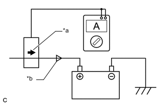
*a Probe Direction *b Current Flowing to Auxiliary Battery Connect the AC/DC 400 A probe of the tester to the positive (+) auxiliary battery cable.
-
Turn the power switch on (READY) and leave the vehicle as it is until the electric current flowing to the auxiliary battery becomes 10 A or less.
-

*a Probe Direction *b Current Flowing from Auxiliary Battery Change the orientation of the AC/DC 400 A probe.
-
Measure the current flowing from the auxiliary battery with the power switch on (READY), the headlight position switch and blower motor switch in the HI position, and the rear window defogger turned on.
Standard Current Item Condition Specified Condition Current flowing from auxiliary battery Power switch on (READY)
(Headlight position switch and blower motor switch in HI position, and rear window defogger on)
0 A or less
(No current from auxiliary battery)
-
Turn the power switch off.
-
-